Error pattern identification in an installed base of systems

a technology of error pattern and installed base, applied in the field of error pattern identification, can solve the problems of complex system deployment, high maintenance cost, and manual analysis of error reports, and achieve the effect of reducing the number of errors

Inactive Publication Date: 2013-11-26
SIEMENS HEALTHCARE GMBH
View PDF28 Cites 21 Cited by
  • Summary
  • Abstract
  • Description
  • Claims
  • Application Information

AI Technical Summary

Problems solved by technology

Complex systems, deployed in geographically dispersed locations, such as magnetic resonance imaging (MRI), computed tomography (CT) and other industrial and medical systems, are expensive to maintain.
The diagnosis of component and subsystem failures by a technician, or by manual analysis of error reports; is both costly and time consuming.
Often the great complexity of such systems means that the error reports describe error states but do not permit a direct conclusion about the defective component.
However, such test routines are time consuming; they may diagnose a failure for which a spare part is not available at the equipment site, and may therefore require further time to acquire the spare part and a subsequent additional technician visit to perform the repair.
In other instances, an on-site test routine may not be feasible for a particular failure type, such as in a closed-loop portion of the system, where additional test fixtures may be needed.
The great complexity of, for example, MRI systems, means that the error reports or error states do not permit a direct conclusion about the defective component causing the failure.
This typically leads to high consumption of spare parts where such parts are replaced without the curing of the defect, longer searches for errors, and a high proportion of returned goods that are not defective.
However, due to the above-described problems, this preliminary diagnosis often cannot unambiguously identify a defective part.

Method used


Image

  • Error pattern identification in an installed base of systems
  • Error pattern identification in an installed base of systems
  • Error pattern identification in an installed base of systems

Examples


Embodiment Construction

[0013]Exemplary embodiments may be better understood with reference to the drawings. Like numbered elements in the same or different drawings perform equivalent functions.

[0014]In the interest of clarity, not all the routine features of the examples herein are described. It will of course be appreciated that in the development of any such actual implementation, numerous implementation-specific decisions must be made to achieve a developers' specific goals, such as consideration of system and business related constraints, and that these goals will vary from one implementation to another.

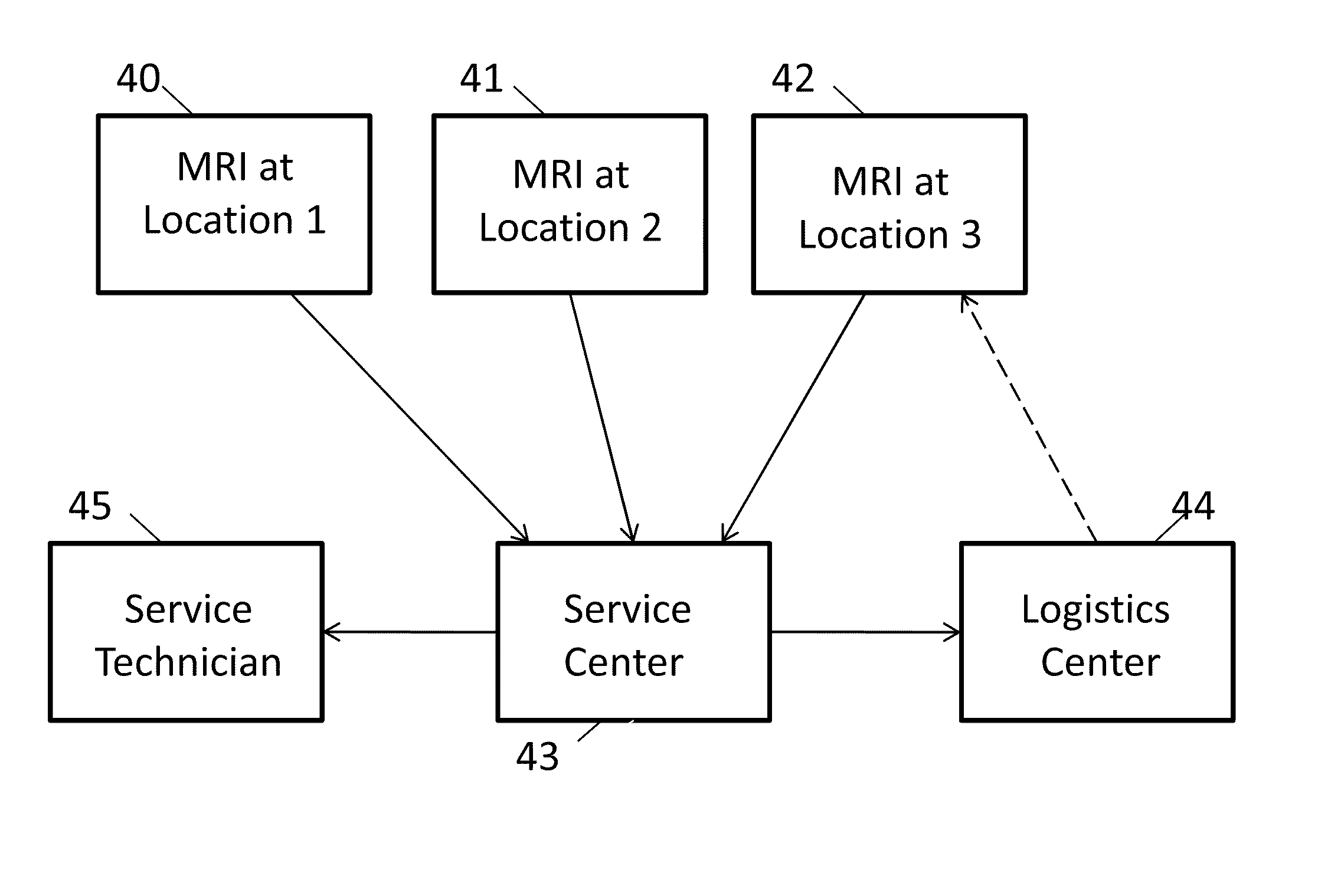
[0015]Systems may be considered to have three phases of a lifetime; development, deployment and support. During the development of a system, the design phase may consider operational requirements and specifications, and may also consider the subsequent servicing and quality control aspects of the deployed system. In particular, sensors or software routines may be developed so as to ensure the proper o...


PUM


Abstract

A system and method of servicing a group of similar types of equipment that maybe installed at geographically separated locations is described. The method makes use of error messages produced by the equipment and service requests received by a servicing center. Data mining techniques are used to establish error patterns associated with specific failure modes so that future error messages may be processed to determine if an identified failure mode has occurred. This will enable the efficient dispatch of spare parts and service personnel to the location where the failure has occurred.

Description

TECHNICAL FIELD[0001]The present application may relate to a system and method of determining a response to a failure of equipment at geographically separate locations.BACKGROUND[0002]Complex systems, deployed in geographically dispersed locations, such as magnetic resonance imaging (MRI), computed tomography (CT) and other industrial and medical systems, are expensive to maintain. The diagnosis of component and subsystem failures by a technician, or by manual analysis of error reports; is both costly and time consuming. Often the great complexity of such systems means that the error reports describe error states but do not permit a direct conclusion about the defective component. That is, in some way the system has failed to perform properly, yet the error reported does not correspond to a uniquely identified component to be replaced, repaired, calibrated, or the like, so as to restore the system to a valid operational state.[0003]Resolving reported errors often requires dispatchin...

Claims


Application Information

Patent Timeline
Patent Type & Authority Patents(United States)
IPC IPC(8): G06F11/00
CPCG05B23/0283G06F19/3412G16H40/40
Inventor GOERTLER, GEORGBERTOSSI, ROBERTSCHULTZ, HARALDRACKOW, BASTIANENGELS, NORBERTHAEUSER, PETER
Owner SIEMENS HEALTHCARE GMBH
Why Eureka
Try Eureka