Water appliance having a flow control unit and a filter assembly

a technology of flow control unit and filter assembly, which is applied in the direction of operating means/releasing devices of valves, separation processes, filtration separation, etc., can solve the problems of water being a scarce and expensive resource, leaking, and lack of access to clean water, so as to prevent water leakage

Inactive Publication Date: 2013-12-03
KONINK PHILIPS ELECTRONICS NV
View PDF48 Cites 50 Cited by
  • Summary
  • Abstract
  • Description
  • Claims
  • Application Information

AI Technical Summary

Benefits of technology

[0004]It is an object of the present invention to provide a water appliance of the kind set forth in the opening paragraph which prevents leakage of water in the absence of a demand for water.
[0013]Such an arrangement is known to be very reliable, easy to manufacture and at relatively low costs.

Problems solved by technology

Lack of access to clean water is a leading cause of death and disease in a lot of countries, killing many people annually and causing a wide variety of illnesses.
In many countries water is a scarce and expensive resource.
Such spillage may occur as a result of leakage caused by e.g. poor maintenance of faucets, faulty pipe connections or worn-out gaskets in various components of water systems or by inattentive closure of faucets, water taps and the like.

Method used


Image

  • Water appliance having a flow control unit and a filter assembly
  • Water appliance having a flow control unit and a filter assembly
  • Water appliance having a flow control unit and a filter assembly

Examples


Embodiment Construction

[0023]In the following figures like reference numerals indicate like or similar components.

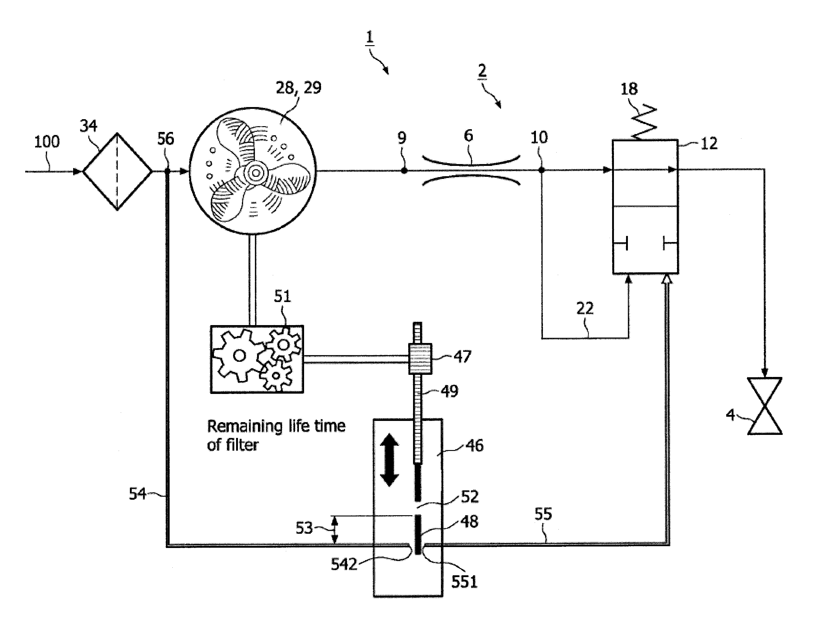
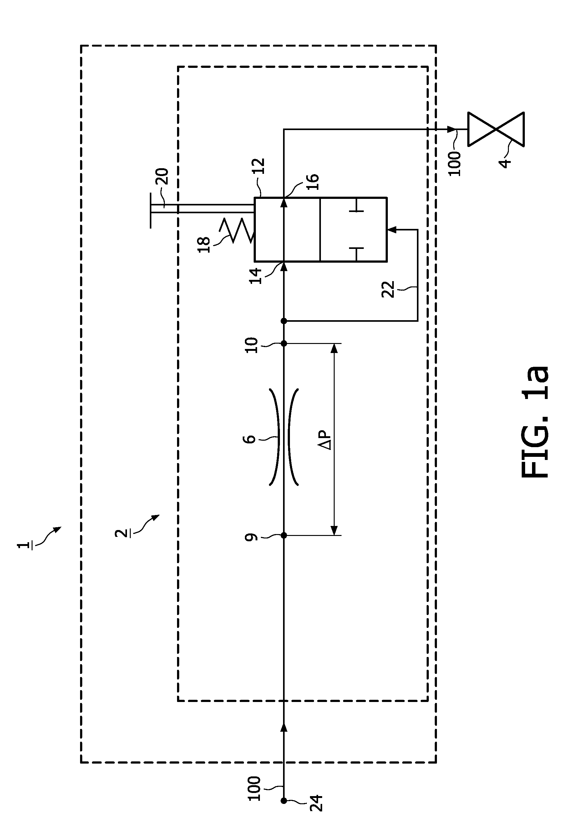
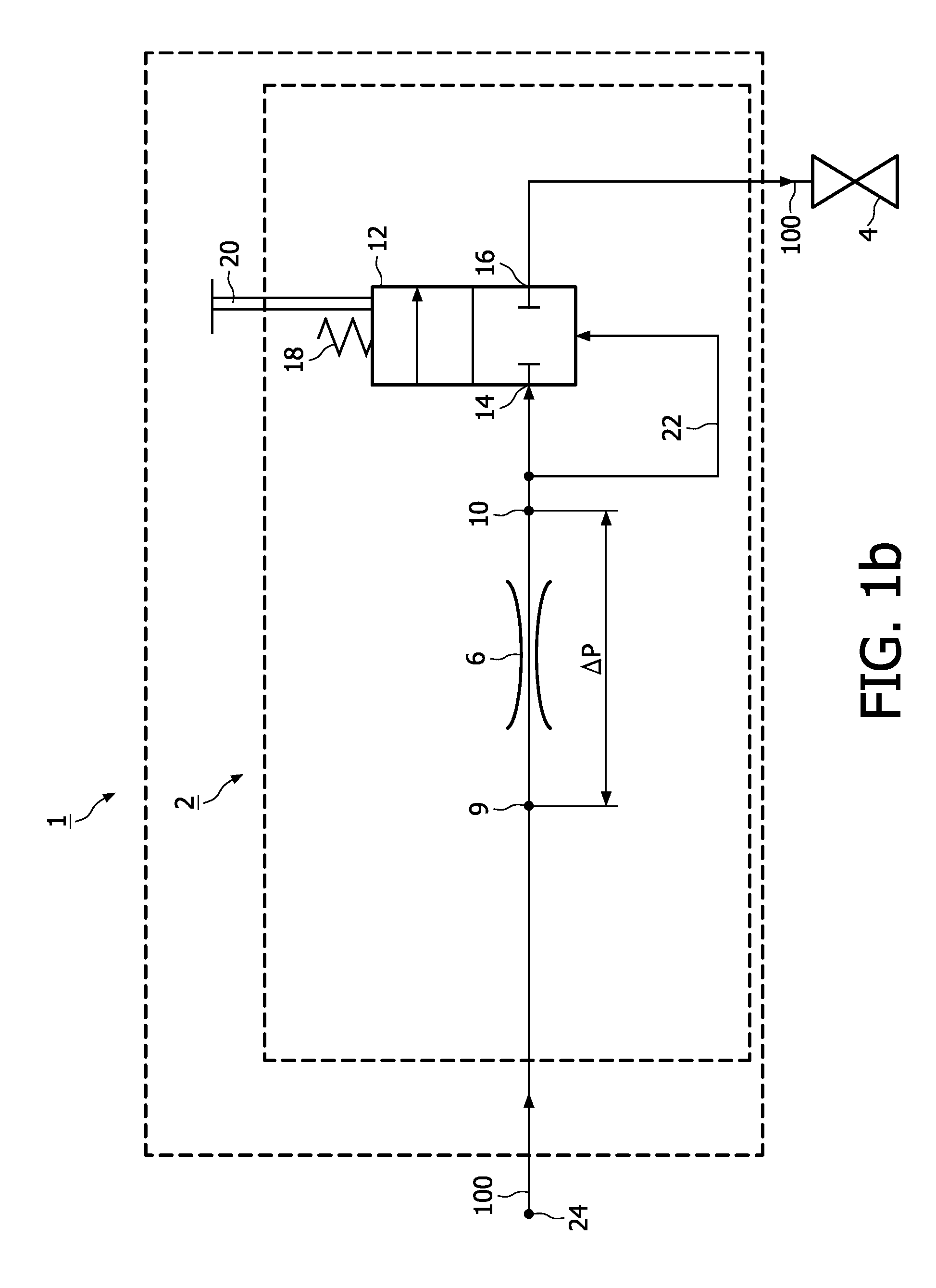
[0024]In FIGS. 1a and 1b a water appliance 1 is schematically depicted by a first striped box. The water appliance 1 has a flow control unit 2 indicated by a second striped box inside the first striped box. A faucet 4 can be opened to enable a water flow 100 through the appliance 1. The water flow 100 is controlled by the flow control unit 2. The flow control unit 2 includes a flow restrictor 6. During normal demand of water the flow 100 through the appliance 1 and through the flow restrictor 6 will cause a drop of pressure ΔP between an inlet 9 of the restrictor 6 and an outlet 10 of the restrictor 6. The flow control unit 2 has a leakage stop 12. The leakage stop 12 is linked into the flow control unit via two connections 14 and 16. The leakage stop 12 has two switch positions. A first switch position is depicted in FIG. 1a. In the first switch position a fluid connection is established betw...


PUM

PropertyMeasurementUnit
pressureaaaaaaaaaa
volumeaaaaaaaaaa
energyaaaaaaaaaa

Abstract

A water appliance including a water flow control unit for controlling a water flow. The control unit includes a flow restrictor and a leakage stop in serial fluid communication with the flow restrictor. The leakage stop cuts off the flow when a pressure difference between an inlet and an outlet of the flow restrictor is below a predetermined value.

Description

FIELD OF THE INVENTION[0001]The invention is related to a water appliance having a water flow control unit for controlling a water flow and to a filter assembly.BACKGROUND OF THE INVENTION[0002]Lack of access to clean water is a leading cause of death and disease in a lot of countries, killing many people annually and causing a wide variety of illnesses. Water treatment is necessary to alleviate the health conditions of people and to protect from the ill effects acquired from the consumption of unsafe or contaminated water. In many countries water is a scarce and expensive resource. Methods for waste water treatment have a wide interest associated with the energy consumed by such water treatment. Although waste water can be recycled and re-used it is generally considered of importance to avoid unnecessary spillage of water. Such spillage may occur as a result of leakage caused by e.g. poor maintenance of faucets, faulty pipe connections or worn-out gaskets in various components of w...

Claims


Application Information

Patent Timeline
Patent Type & Authority Patents(United States)
IPC IPC(8): F16K21/18
CPCF16K17/30F17D5/02F17D3/01F17D3/18Y10T137/742Y10T137/7485Y10T137/7378Y10T137/7446Y10T137/794Y10T137/7323Y10T137/7761Y10T137/7329Y10T137/7465Y10T137/7287B01D35/00B01D35/153
Inventor MOUS, FRANSDE JONGE, SANDER
Owner KONINK PHILIPS ELECTRONICS NV
Why Eureka
Try Eureka