Surgical instrument

a surgical instrument and instrument technology, applied in the field of surgical instruments, can solve the problems of difficult sterilization, complicated manufacturing and use of devices, delay in surgical procedures, etc., and achieve the effect of affecting the orthopaedic implan

Active Publication Date: 2013-12-03
DEPUY (IRELAND) LTD
View PDF11 Cites 3 Cited by
  • Summary
  • Abstract
  • Description
  • Claims
  • Application Information

AI Technical Summary

Benefits of technology

[0022]As different formations of the same head are used to engage different portions of the same or different components of the orthopaedic implant, the same impactor can be used to reliably impact the orthopaedic implant.

Problems solved by technology

Often bone cement is also used to secure the implant to the bone, but there is usually a tight or interference fit between the implant component.
However, use of such an impactor can cause delays in the surgical procedure as it is necessary to swap the heads.
Also, such devices are more complex to manufacture and use and can be difficult to sterilise owing to the mechanical attachment mechanism for the different heads.
Also, some of impactor heads can be attached to the implants, but then tend to be useable only with a specific implant and again are more complex to manufacture and harder to sterilise.
More simple impaction devices are also available which can be used generally for impaction but do not have any inbuilt features to perform the specific impaction tasks required.
This can lead to damage of the implant components due to scratching of the bearing surfaces and / or deformations and hence have limited utility.

Method used


Image

  • Surgical instrument
  • Surgical instrument
  • Surgical instrument

Examples


Embodiment Construction

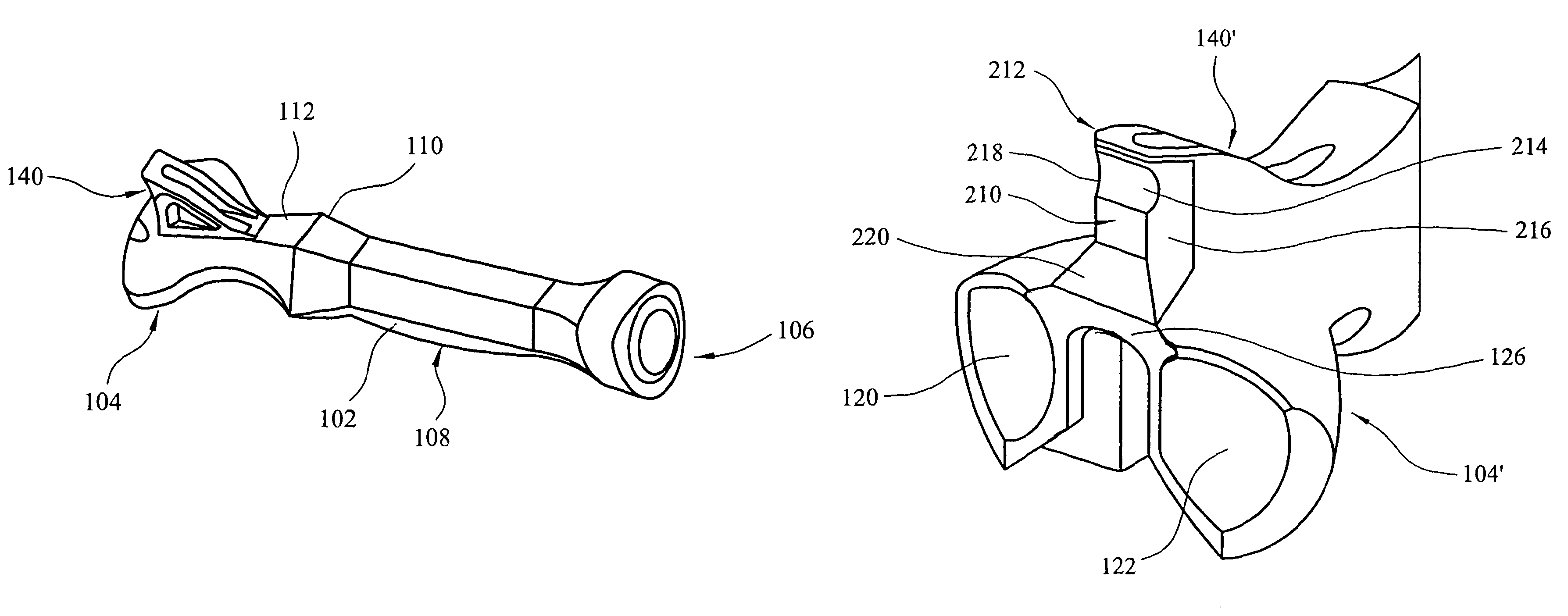
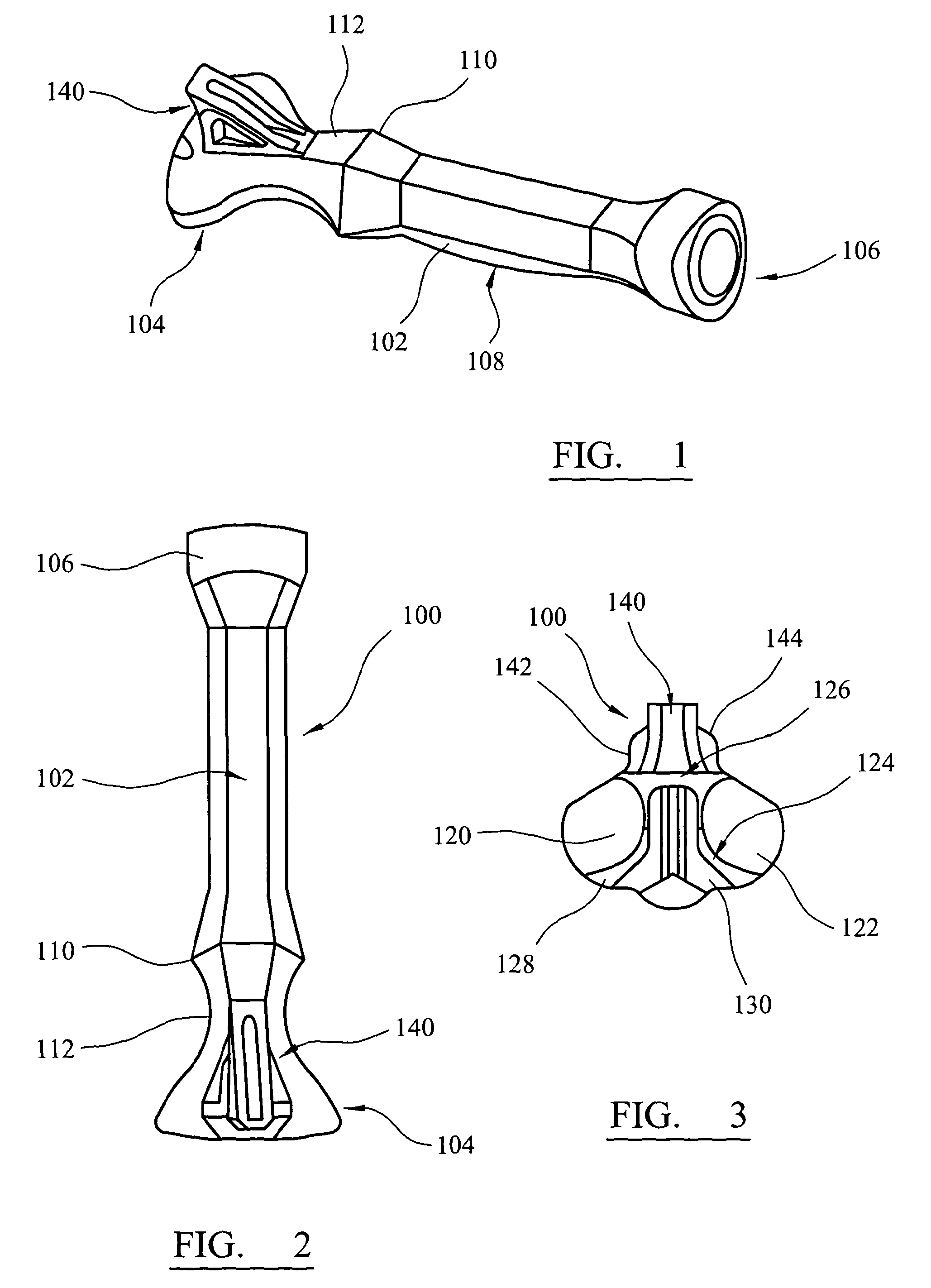
[0039]With reference to FIG. 1 there is shown a multi-function impactor 100 according to the present invention. The impactor 100 generally has a central shaft portion 102 and has a head 104 at a first distal end and also has a second proximal end 106. The second end 106 has a generally rounded triangular form with a central slightly raised circular portion which provides a strike zone for receiving a blow from a tool, such as a hammer or mallet, in use. A portion of the shaft below the second end forms a handle by which the impactor can be gasped in use. The handle portion of the shaft has a slightly bulging portion 108 to facilitate grip thereof by the user. A slightly thicker, flared portion 110 defines the lower part of the handle and the shaft then narrows to a neck region 112 before flaring into the impactor head 104.

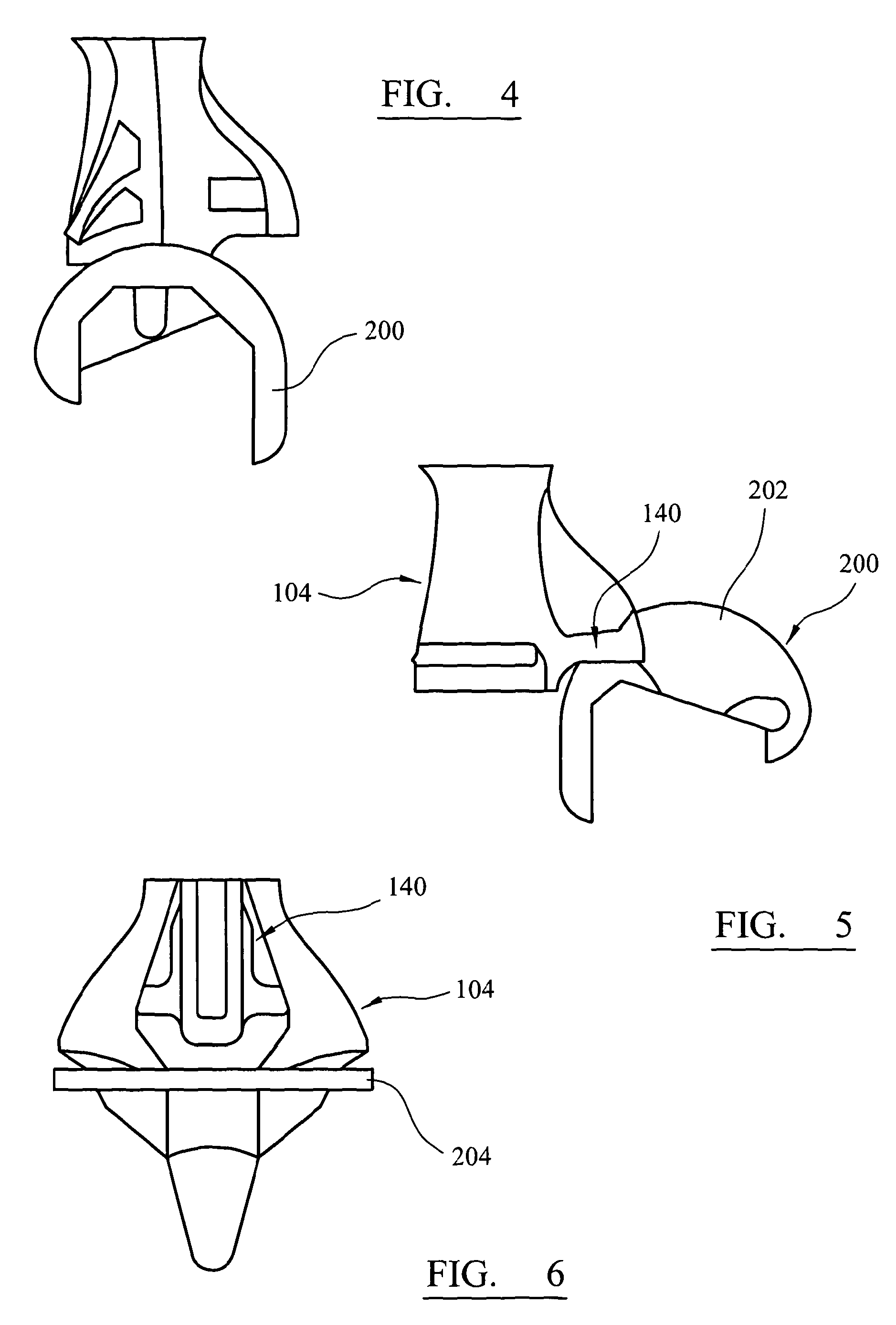
[0040]As can best be seen in FIG. 3, the impactor head 104 has a number of formations which are shaped, spaced, sized, positioned and otherwise configured to engag...


PUM


Abstract

A multi-function impactor for use with an orthopaedic implant, such as a knee joint, is described. The head of the impactor has a pair of curved recesses for mating with condylar parts of a femoral implant and flat faces for mating with a tibial implant. An extended formation is also provided for use with the inter-condylar notch of the femoral implant. A v-shaped notch in the extended formation is also provided to impact a tibial insert. The impactor can be made from a single moulded plastics part.

Description

CROSS REFERENCE TO RELATED APPLICATION[0001]This application is a National Stage 35 U.S.C. 371 of International Patent Application PCT / GB2010 / 001278 filed Jul. 1, 2010BACKGROUND OF THE INVENTION[0002]The present invention relates to a surgical instrument, and in particular to an impactor for use with orthopaedic implants.[0003]Impactors are used during orthopaedic arthroplasty procedures to drive the implant components onto the bone. Often bone cement is also used to secure the implant to the bone, but there is usually a tight or interference fit between the implant component. Hence, a tool, such as a mallet, hammer or similar, is used to drive the implant component onto the bone, by hitting a free end of the impactor, while the impactor engages the implant. However, it is important to ensure that an even pressure is applied to the component, so that it seats correctly on the resected bone surface, and also that the bearing surfaces are not damaged during impaction. Hence, different...

Claims


Application Information

Patent Timeline
Patent Type & Authority Patents(United States)
IPC IPC(8): A61B17/58A61B17/60A61F2/00
CPCA61F2/461A61F2/3859A61F2/389A61F2/3886
Inventor BEEDALL, DUNCANFISHER, DAVIDGHOSH, SOURAV
Owner DEPUY (IRELAND) LTD
Why Eureka
Try Eureka