

Apparatus and method for size reduction
a technology of apparatus and material, applied in the direction of lighting and heating apparatus, working up peat, gas current separation, etc., can solve the problems of undegraded material exiting the chamber and hitting the impeller, and achieve the effect of reducing the size of the material
- Summary
- Abstract
- Description
- Claims
- Application Information
AI Technical Summary
Benefits of technology
Problems solved by technology
Method used
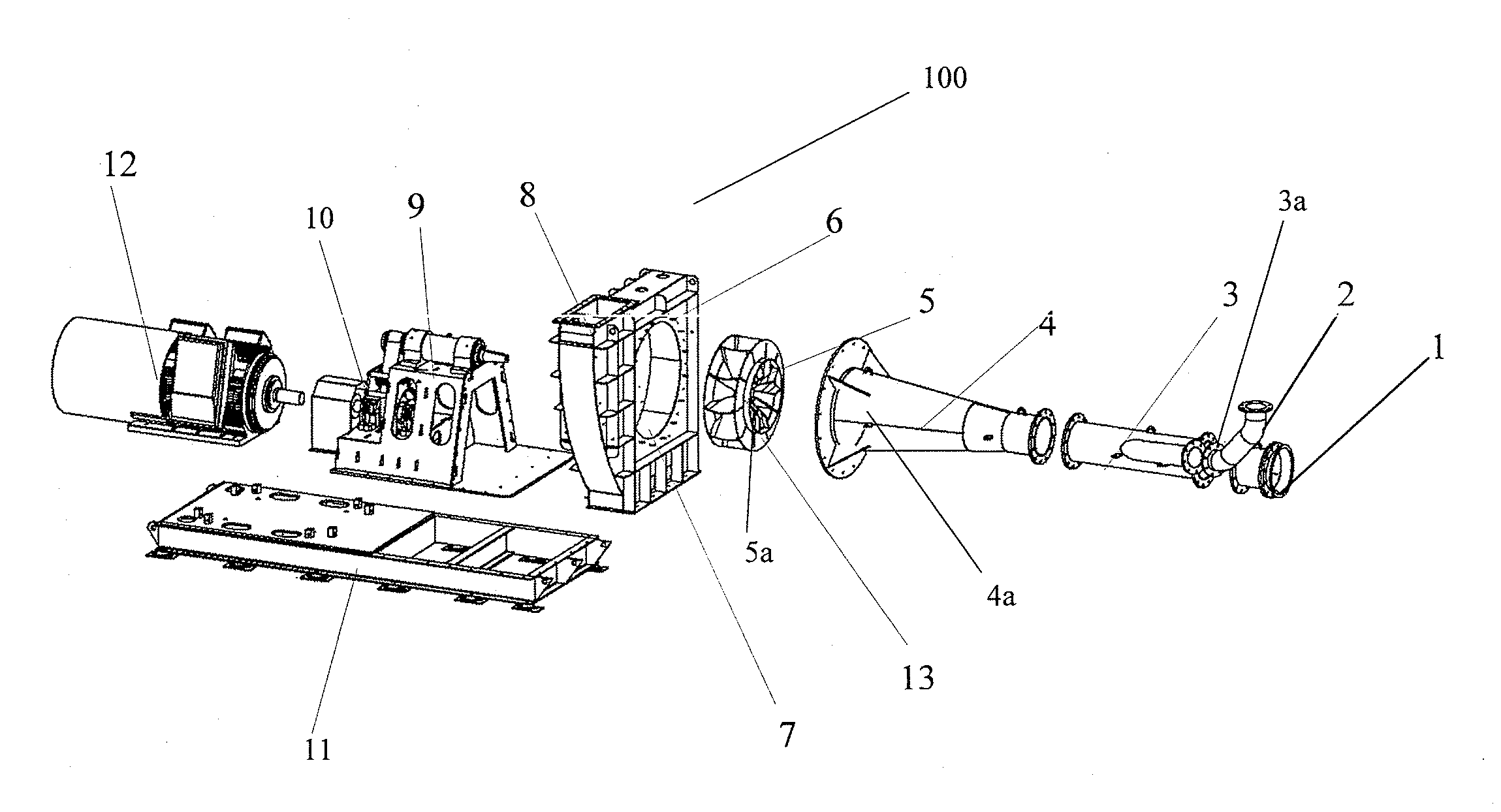
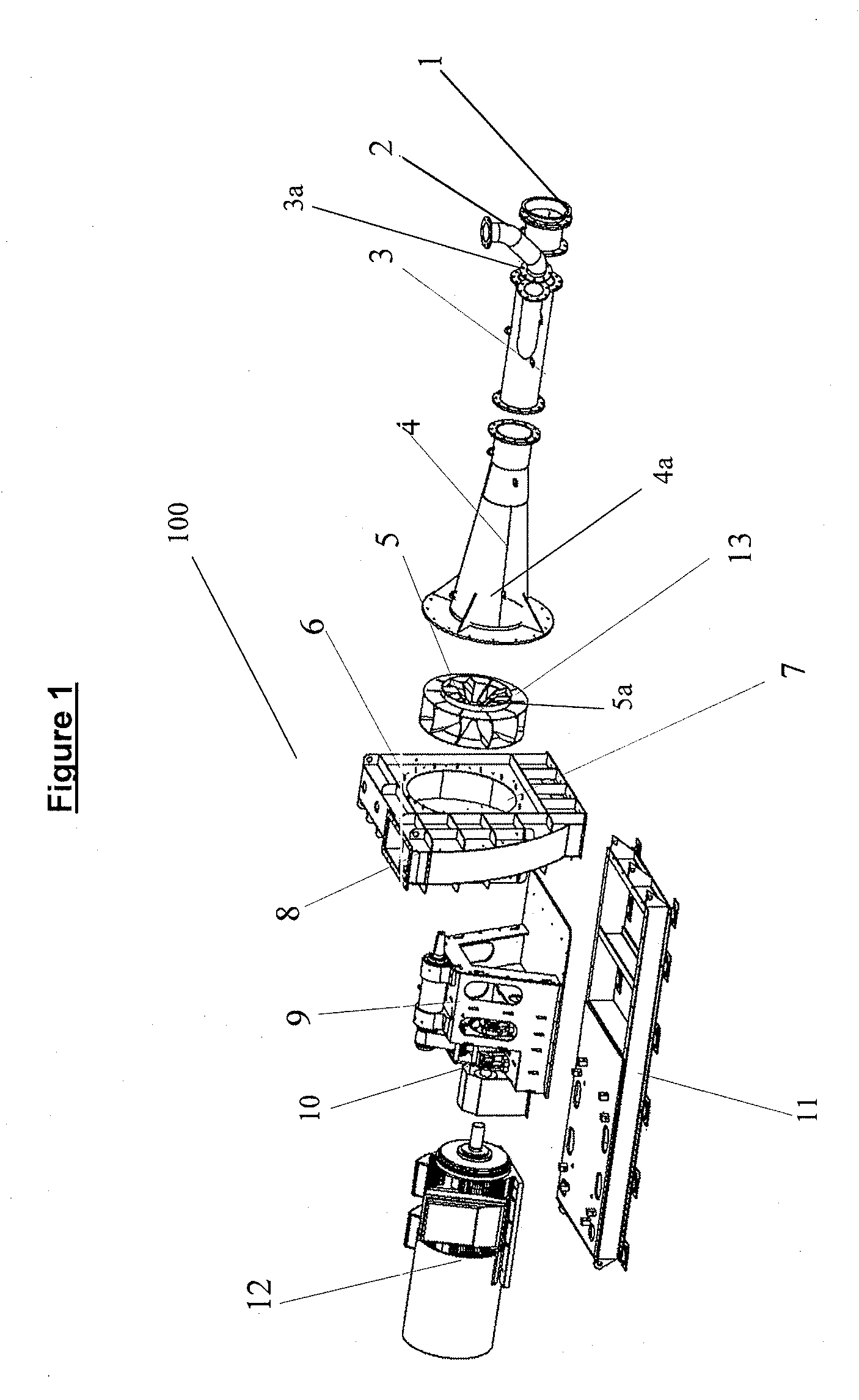
Image

Examples
example 1
[0191]The following example exemplifies the determination of a suitable range of kinematic viscosity (ν) within which to carry out the method according to any aspect of the present invention.
[0192]The Moody Diagram can be represented by the Colebrook White equation:
[0193]f-1 / 2=-4log[(ks3.71d)+(1.26f-1 / 2Re)]Equation(1)
[0194]where:
[0195]f is the friction factor (often referred to as λ in the Moody Diagram where λ=4f);
[0196]ksd
represents the relative pipe roughness; and
[0197]Re represents the Reynolds number.
[0198]Equation 1 can be solved iteratively for f for known values of Re and
[0199]ksd.
[0200]Re=udvEquation(2)
[0201]where:
[0202]u is the airflow (fluid) velocity through the pipe;
[0203]d is the diameter of the pipe
[0204]ν is the kinematic viscosity of the material being processed.
[0205]v=μρEquation(3)
[0206]where:
[0207]μ is the dynamic viscosity
[0208]ρ is the density.
[0209]The pressure drop in the pipe is represented by Equation (4) as follows:
ΔP=hfρg Equation (4)
[0210]whe...
example 2
[0228]A sample of brown coal sourced from Victoria, Australia, is split into two. One batch was prepared using the apparatus described above (batch is hereinafter referred to as “Sample A”). The second batch (hereinafter referred to as “Sample B”) was dried and milled using industry standard coal preparation milling method as described in ASTM D2013-07 (Standard practice for preparing coal samples for analysis).
[0229]Both the coal samples were both subjected to the following analysis:[0230]a) Proximate and Ultimate analyses—measuring moisture, ash, volatile matter, sulphur, chlorine, Gross Calorific value, Net Calorific Value;[0231]b) Size analysis;[0232]c) Intrinsic reactivity; and[0233]d) Scanning Electron microscopy-Energy Dispersive Spectrometry (SEM-EDX).
[0234]Each of the above analyses and their results will be described in detail below.
[0235]a) Proximate and Ultimate Analyses
[0236]The proximate analysis was carried out using the standard ASTM (American Society for Testing and...
example 3
[0256]A sample of Bauxite material from Queensland, Australia with a moisture content of 16% was obtained. The effect of the addition of viscosity modifying agent on the sample was tested. The viscosity modifying agents chosen were heated air with a temperature of approximately 50° C. and a mist spray of water. Ambient temperature and humidity were 26° C. and 30%, respectively.
[0257]Tests were then conducted by adding heat and then repeated by adding moisture.
[0258]1. Baseline Test, no water or heat added: Moisture of the sample was reduced to 7%.
[0259]2, Heated air added to air intake: Moisture of the sample was reduced to 9%.
[0260]3. Mist spray added to air intake: Moisture of the sample was reduced to 4%.
PUM
| Property | Measurement | Unit |
|---|---|---|
| kinematic viscosity | aaaaa | aaaaa |
| Reynolds number | aaaaa | aaaaa |
| Reynolds number | aaaaa | aaaaa |
Abstract
Description
Claims
Application Information