Airborne, tethered, remotely stabilized surveillance platform

a surveillance platform and remote stabilizer technology, applied in vehicle position/course/altitude control, process and machine control, instruments, etc., can solve the problems of observation sensors not being able to provide a full-circle view of the surrounding terrain, positioning devices not suitable for maintaining a surveillance platform in a horizontal position, and sensor suite lacks a vertical control loop

Inactive Publication Date: 2013-12-10
PETROV DIMITRI
View PDF5 Cites 47 Cited by
  • Summary
  • Abstract
  • Description
  • Claims
  • Application Information

AI Technical Summary

Problems solved by technology

However, the positioning device is not suitable for maintaining a surveillance platform in a horizontal position since it relies solely on the aerodynamics of the supporting vehicle to meet this requirement.
Consequently; the observation sensors cannot provide a full-circle view of the surrounding terrain.
Furthermore, the sensor suite lacks a vertical control loop that would ensure a stable image to the operator.
It has also the disadvantage of being visible from afar and failing to operate in winds over 50 mph.
Their main disadvantage is their tendency to drift and become unstable in crosswinds.
This surveillance system has the tactical disadvantage of operating only when the vehicle is stationary.

Method used


Image

  • Airborne, tethered, remotely stabilized surveillance platform
  • Airborne, tethered, remotely stabilized surveillance platform
  • Airborne, tethered, remotely stabilized surveillance platform

Examples


Embodiment Construction

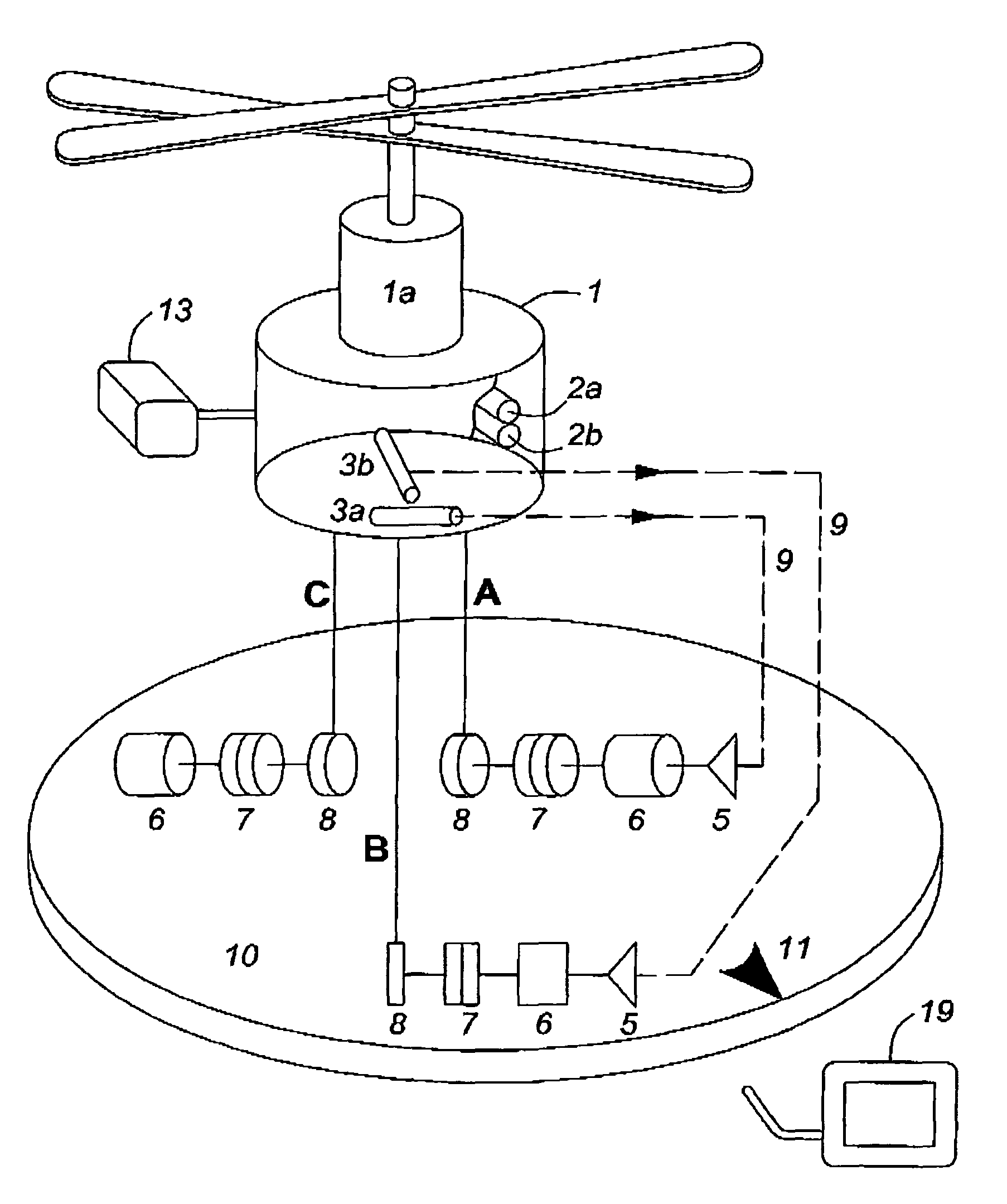
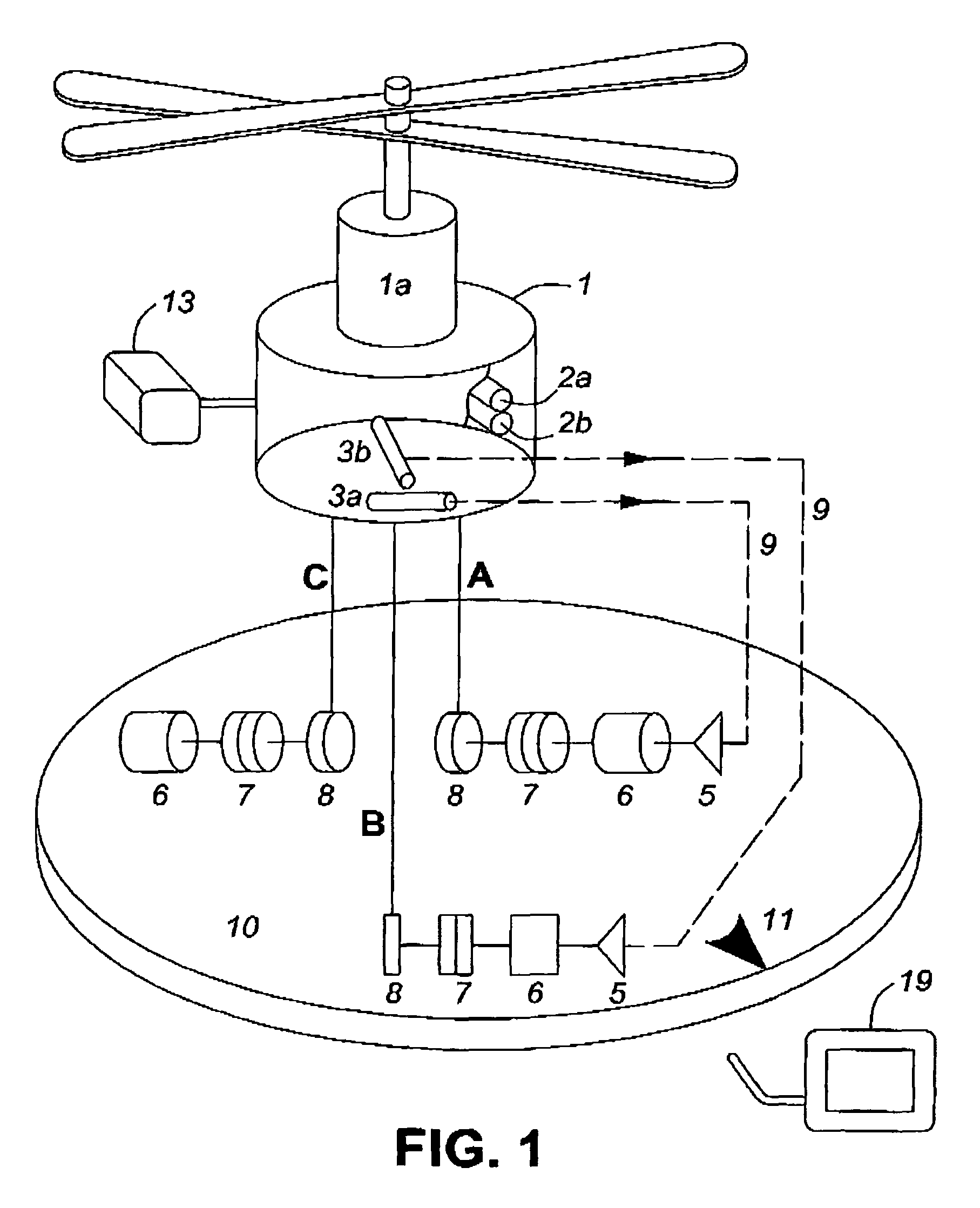
[0019]The functional schematic of airborne surveillance platform 1 is illustrated in FIG. 1. Two counter-rotating propellers are driven by electric motor 1a, which receives the required energy from an on-board battery or from a power supply in the vehicle via the conductive tethers. With clutches 7 disengaged, three tethers A, B and C are paid out by reels 8 until the platform reaches an altitude determined by the length of tether C. The reel drives are 120° degrees apart. At this stage, all three clutches 7 are engaged and the tethers are under tension. While the length of tether C remains fixed, the lengths of tethers A and B are adjusted by means of two positional servo-loops as follows. First, the error signal from level sensor 3a is transmitted over wireless link 9 to amplifier 5 which drives motor 6 and reel 8, until the length of tether A is adjusted so that the error signal is minimized and level sensor 3a is horizontal. This sequence of events is then repeated by the servo-...


PUM


Abstract

An airborne surveillance platform supporting optoelectronic and electronic sensors, including level sensors, is automatically stabilized in a horizontal plane by varying the length of two tethers out of three. Error signals from the level sensors are transmitted over a wireless link to control components on a rotating platform on the host vehicle, which automatically vary the length of tethers. Applications include images of the surrounding terrain generated by a video camera and a thermal imager in military, police and civil emergency operations.

Description

CROSS-REFERENCE TO RELATED APPLICATIONS[0001]This application claims the benefit of provisional patent application Ser. No. 61 / 269,000 filed on 19 Jun. 2009, by the present inventor.FEDERALLY SPONSORED RESEARCH[0002]Not applicableSEQUENCE LISTING[0003]Not applicableBACKGROUND[0004]1. Field[0005]This application relates to airborne surveillance platforms.[0006]2. Prior Art[0007]There is a need for airborne platforms supporting electronic and optoelectronic sensors for gathering meteorological data and for transmitting images of the surrounding terrain in military, police and civil emergency applications[0008]Crosby describes in U.S. Pat. No. 2,433,344 an aeronautic positioning device that automatically stabilizes a balloon, and airplane or a helicopter in a desired position above the earth, irrespective of wind and atmospheric conditions. The aerial vehicle supports a radio antenna of meteorological equipment. However, the positioning device is not suitable for maintaining a surveill...

Claims


Application Information

Patent Timeline
Patent Type & Authority Patents(United States)
IPC IPC(8): B64C27/10
CPCB64C39/022B64C39/024B64C2201/027B64C2201/208B64C2201/108B64C2201/127B64C2201/148B64C2201/042G05D1/0866B64U10/13B64U50/19B64U30/20B64U2101/30B64U2201/202B64U80/86
Inventor PETROV, DIMITRI
Owner PETROV DIMITRI
Why Eureka
Try Eureka