System and method for displaying a velocity rate-of-change indicator

a technology of velocity rate and indicator, applied in the field of vehicle display system, can solve the problems of difficulty for pilots to discern if the target is rapidly accelerating, rapidly decelerating, and excessive pilot attention, and achieve the effect of reducing the amount of pilot attention required and consuming excessive tim

Active Publication Date: 2013-12-10
HONEYWELL INT INC
View PDF12 Cites 8 Cited by
  • Summary
  • Abstract
  • Description
  • Claims
  • Application Information

AI Technical Summary

Problems solved by technology

However, the velocity vector does not indicate whether the traffic target is accelerating, decelerating, or maintaining a substantially constant velocity.
Therefore, when a pilot only briefly reviews the CDTI, it is difficult for the pilot to discern if the target is rapidly accelerating (as would be the case when, for example, an aircraft is taking off) or rapidly decelerating (as would be the case when an aircraft has just landed).
The amount of pilot attention this would require and the time consumed thereby are excessive given the pilot's priority for out-the-window scanning in the terminal area.

Method used


Image

  • System and method for displaying a velocity rate-of-change indicator
  • System and method for displaying a velocity rate-of-change indicator
  • System and method for displaying a velocity rate-of-change indicator

Examples


Embodiment Construction

[0020]The following Detailed Description is merely exemplary in nature and is not intended to limit the invention or the application and uses of the invention. Furthermore, there is no intention to be bound by any theory presented in the preceding Background or the following Detailed Description.

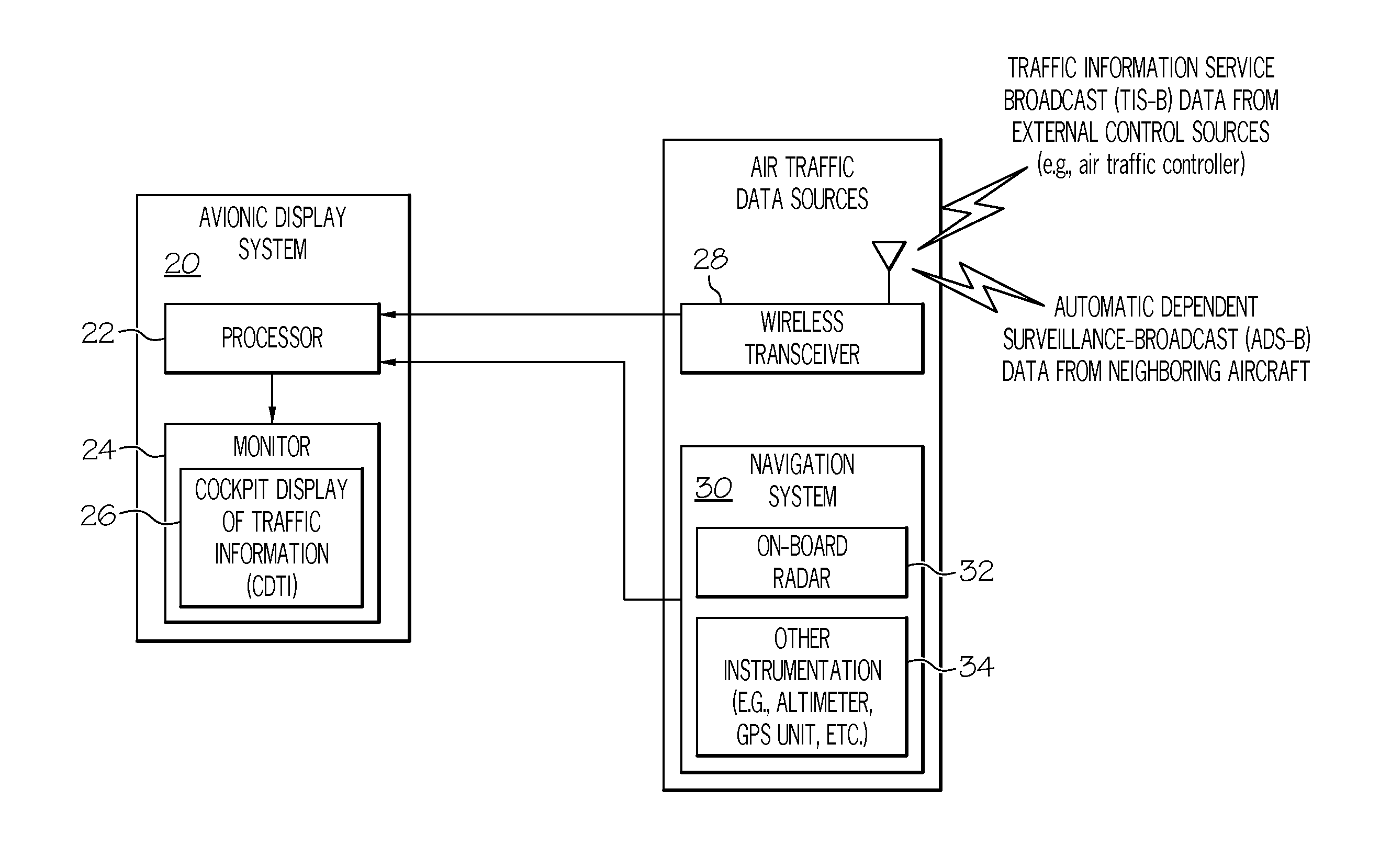
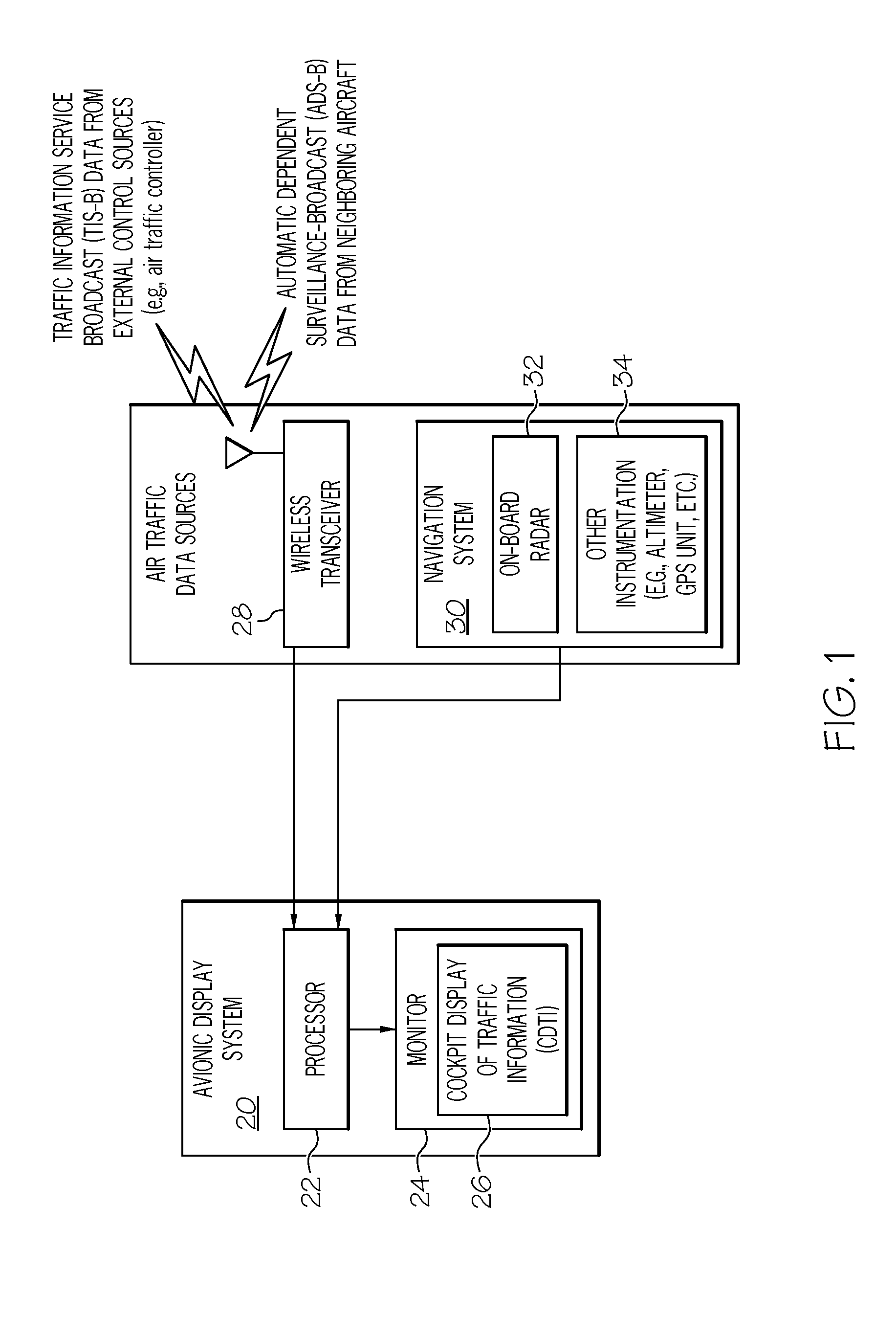
[0021]FIG. 1 is functional block diagram that includes a generalized avionics display system 20 in accordance with an exemplary embodiment. Avionics display system 20 includes at least one processor 22 and at least one monitor 24, which is operatively coupled to processor 22. During operation of avionics display system 20, processor 22 drives monitor 24 to produce a graphical display 26 that visually provides a pilot and crew with navigational informational pertaining to the host aircraft and to neighboring aircraft within a predetermined vicinity of the host aircraft. Graphical display 26 may include visual representations of one or more of flight characteristics pertaining to a neighboring...


PUM


Abstract

Avionics display system is provided for deployment onboard an aircraft and includes an air traffic data source that provides the avionics display system with data indicative of at least position and velocity of a neighboring aircraft. The system comprises a cockpit display system, and a monitor included within the cockpit display system. The cockpit display system receives and displays position and velocity data pertaining to the neighboring aircraft on the cockpit monitor as a position symbol and a velocity vector graphic. A processor operatively coupled to the monitor is configured to generate an air traffic display on the monitor including symbology indicative of (1) the current position of the neighboring aircraft (2) a velocity of the neighboring aircraft, and (3) the rate-of-change of the velocity of the neighboring aircraft.

Description

TECHNICAL FIELD[0001]Embodiments of the subject matter described herein relate generally to vehicular display systems and, more particularly, to an avionics display system for visually expressing flight information on a host aircraft that pertains to the position, velocity and velocity rate-of-change, of a neighboring aircraft.BACKGROUND[0002]Advances in aircraft surveillance technology, such as Automatic Dependent Surveillance-Broadcast (ADS-B), support a number of airborne and ground applications; e.g. CDTI (Cockpit Display of Traffic Information) and ACAS (Airborne Collision Avoidance). Among other things, ADS-B provides traffic position and velocity data that can be processed to present a velocity vector associated with a target or neighboring aircraft; i.e. display a line that extends from the displayed traffic symbology and represents the horizontal position of the neighboring aircraft in fifteen seconds. Such traffic data may be presented to one or more onboard displays inclu...

Claims


Application Information

Patent Timeline
Patent Type & Authority Patents(United States)
IPC IPC(8): G08B21/00
CPCG01C23/00G08G5/0008G08G5/0021G08G5/0078
Inventor WHITLOW, STEPHENFLASAR, JANREUSSER, TRENT
Owner HONEYWELL INT INC
Why Eureka
Try Eureka