Printing apparatus and printing method

a printing apparatus and printing method technology, applied in the field of printing apparatus and printing method, can solve the problems of density unevenness and stripes in images, density fluctuation, density unevenness of images,

Inactive Publication Date: 2013-12-17
CANON KK
View PDF25 Cites 17 Cited by
  • Summary
  • Abstract
  • Description
  • Claims
  • Application Information

AI Technical Summary

Benefits of technology

[0019]The first aspect of the present invention is a printing apparatus prints by making a printing head do printing scan for a unit area of the print medium by 2M times (M is an integer larger than 1) comprising: dividing unit which divides image data that should be printed in the unit area into 2M pieces of image data for the 2M times printing scan (Pass 1 to Pass 2M) by using a mask: the mask setting printable areas included in the unit area for each of the 2M times printing scan respectively, so that plural dots of the same type of color may be printed at the same area at least by two printing scan; and Printing unit which prints dots in the printable areas by each of the 2M times printing scan (Pass 1 to Pass 2M) according to the divided image data; wherein the mask is configured so that i) a ratio of the printable areas in which printing is permitted both by passes performed before Pass (M+1) and by passes performed after Pass M is larger than a ratio of the printable areas in which printing is permitted both by passes performed before Pass N+1 (N is an integer differing from M and smaller than 2M) and by passes performed after Pass N, ii) a ratio of the printable areas in which printing is permitted both by passes performed before Pass (M−L+1) (L is a positive integer smaller than M) and by passes performed after Pass (M−L) is smaller than a ratio of the printable areas in which printing is permitted both by passes performed before Pass (M−L+2) and by passes performed after Pass (M−L+1), and a ratio of the printable areas in which printing is permitted both by passes performed before Pass (M+L+1) and by passes performed after Pass (M+L) is larger than a ratio of the printable areas in which printing is permitted both by passes performed before Pass (M+L+2) and by passes performed after Pass (M+L+1), iii) as for at least one combination of S and T (S and T are different and positive integer smaller than 2M), a difference between a ratio of the printable areas in which printing is permitted between both by passes performed before Pass (S+1) and by passes performed after Pass S and a ratio of the printable areas in which printing is permitted between both by passes performed before Pass (S+23) and by passes performed after Pass (S+21), is different from a difference between a ratio of the printable areas in which printing is permitted between both by passes performed before Pass (T+1) and bypasses performed after Pass T and a ratio of the printable areas in which printing is permitted between both by passes performed before Pass (T+23) and by passes performed after Pass (T+12).
[0021]The third aspect of the present invention is a printing method for printing by making a printing head do printing scan for a unit area of the print medium by 2M times (M is an integer larger than 1) comprising: dividing step to divide image data that should be printed in the unit area into 2M pieces of image data for the 2M times printing scan (Pass 1 to Pass 2M) by using a mask: the mask setting printable areas included in the unit area for each of the 2M times printing scan respectively, so that plural dots of the same type of color may be printed at the same area at least by two printing scan; and Printing step to print dots in the printable areas by each of the 2M times printing scan (Pass 1 to Pass 2M) according to the divided image data; wherein the mask is configured so that i) a ratio of the printable areas in which printing is permitted both by passes performed before Pass (M+1) and by passes performed after Pass M is larger than a ratio of the printable areas in which printing is permitted both by passes performed before Pass (N+1) (N is an integer differing from M and smaller than 2M) and by passes performed after Pass N, ii) a ratio of the printable areas in which printing is permitted both by passes performed before Pass (M−L+1) (L is a positive integer smaller than M) and by passes performed after Pass (M−L) is smaller than a ratio of the printable areas in which printing is permitted both by passes performed before Pass (M−L+2) and by passes performed after Pass (M−L+1), and a ratio of the printable areas in which printing is permitted both by passes performed before Pass (M+L+1) and by passes performed after Pass (M+L) is larger than a ratio of the printable areas in which printing is permitted both by passes performed before Pass (M+L+2) and by passes performed after Pass (M+L+1), iii) as for at least one combination of S and T (S and T are different and positive integer smaller than 2M), a difference between a ratio of the printable areas in which printing is permitted both by passes performed before Pass (S+1) and by passes performed after Pass S and a ratio of the printable areas in which printing is permitted both by passes performed before Pass (S+23) and by passes performed after Pass (S+12), is different from a difference between a ratio of the printable areas in which printing is permitted both by passes performed before Pass (T+1) and by passes performed after Pass T and a ratio of the printable areas in which printing is permitted both by passes performed before Pass (T+32) and by passes performed after Pass (T+12).

Problems solved by technology

In the printing head, there is a case where variation arises in a discharge amount and a discharge direction among the printing elements, such variations may cause occurrence of density unevenness and stripes in an image.
However, in recent years, density variation and the density unevenness resulting from a shift of a print position (registration) in printing scan quantities or in printing head (nozzle row) quantities have become to be newly considered as problems because of performing the above-mentioned multipass printing.
Then, if the shift between planes occurs, coverage of the dots relative to the print medium will vary, which will invite density fluctuation and the density unevenness of an image.
Therefore, conveyance at each time becomes unstable or a variation of head-medium distance becomes easy to occur, which makes the shift between planes occur.
However, in the case where a mask whose ratio of printable pixels corresponding to a part of printing scans is reduced is used like Japanese Patent Laid-Open No. 2002-144637, there arises a possibility that an original effect of the multipass printing, that is, an effect of obtaining a smooth image by dispersing influences of the individual printing elements is impaired.
Moreover, since a timing at which the ink is given to the unit area of the print medium by a plurality of printing scans and its quantity will differ in each unit area, the density unevenness accompanying this will also be brought about.
Furthermore, increasing the printing ratio of a part of the printing head becomes a cause of shortening the life of the printing head.
Moreover, in Japanese Patent Laid-Open No. 2002-144637, since the above-mentioned special mask is used especially only to the head part and the tail part of the print medium, the apparatus cannot respond to a conveyance shift that occurs suddenly in a central part of the print medium and the like.
That is, also when the print position shift between a plurality of printing scans suddenly occurs, it is a difficult situation to print an image that is uniform and smooth in the whole area of the print medium.

Method used


Image

  • Printing apparatus and printing method
  • Printing apparatus and printing method
  • Printing apparatus and printing method

Examples


first embodiment

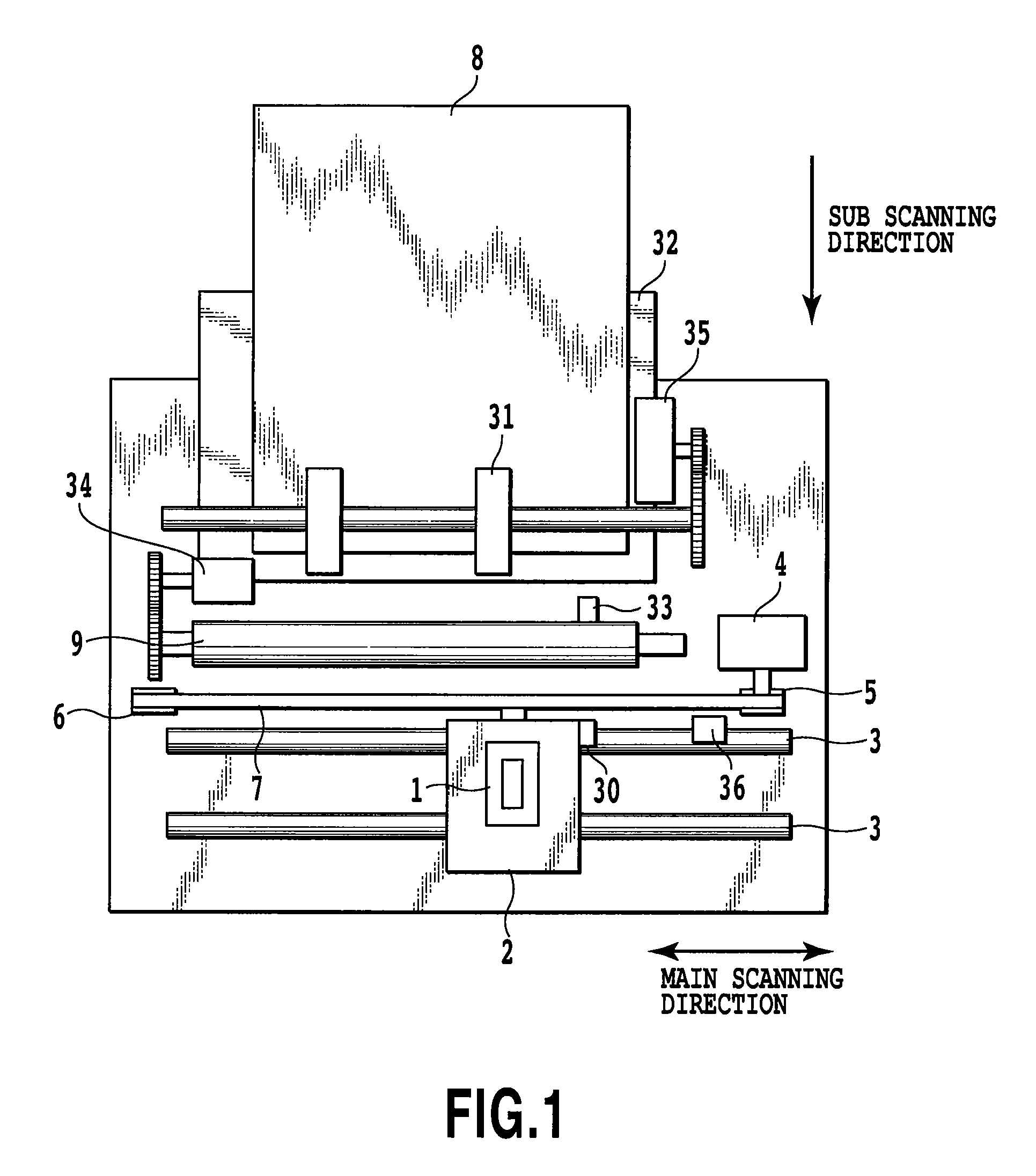
[0063]FIG. 1 is a diagram showing a fundamental configuration of a main mechanism part of an ink jet printing apparatus to which the present invention can be applied. A head cartridge 1 consists of a printing head 201, an ink tank part, and a connector for delivering and receiving a signal for driving the printing head, etc. (not illustrated). Moreover, the head cartridge 1 is mounted on a carriage 2 exchangeably, and the carriage 2 is provided with a connector holder (electric connection part) for transmitting a driving signal etc. to the head cartridge 1 through the connector.0025]

[0064]The carriage 2 is guided and supported in a reciprocation movable manner by a guide shaft 3 which extends along a main scanning direction and is installed in the apparatus main frame. In addition, the carriage 2 is driven by a main scanning motor 4 through a drive mechanism of a motor pulley 5, a following pulley 6, a timing belt 7, etc. and is controlled with respect to position and translation. M...

second embodiment

[0146]Also in this embodiment, the same printing apparatus as that of the first embodiment shown in FIG. 1 is used. Moreover, regarding the control configuration, the block diagram shown in FIG. 2 shall be applicable. In this embodiment, the arrangement configuration of the nozzle row of each color in the printing head 201 differs from that of the first embodiment.

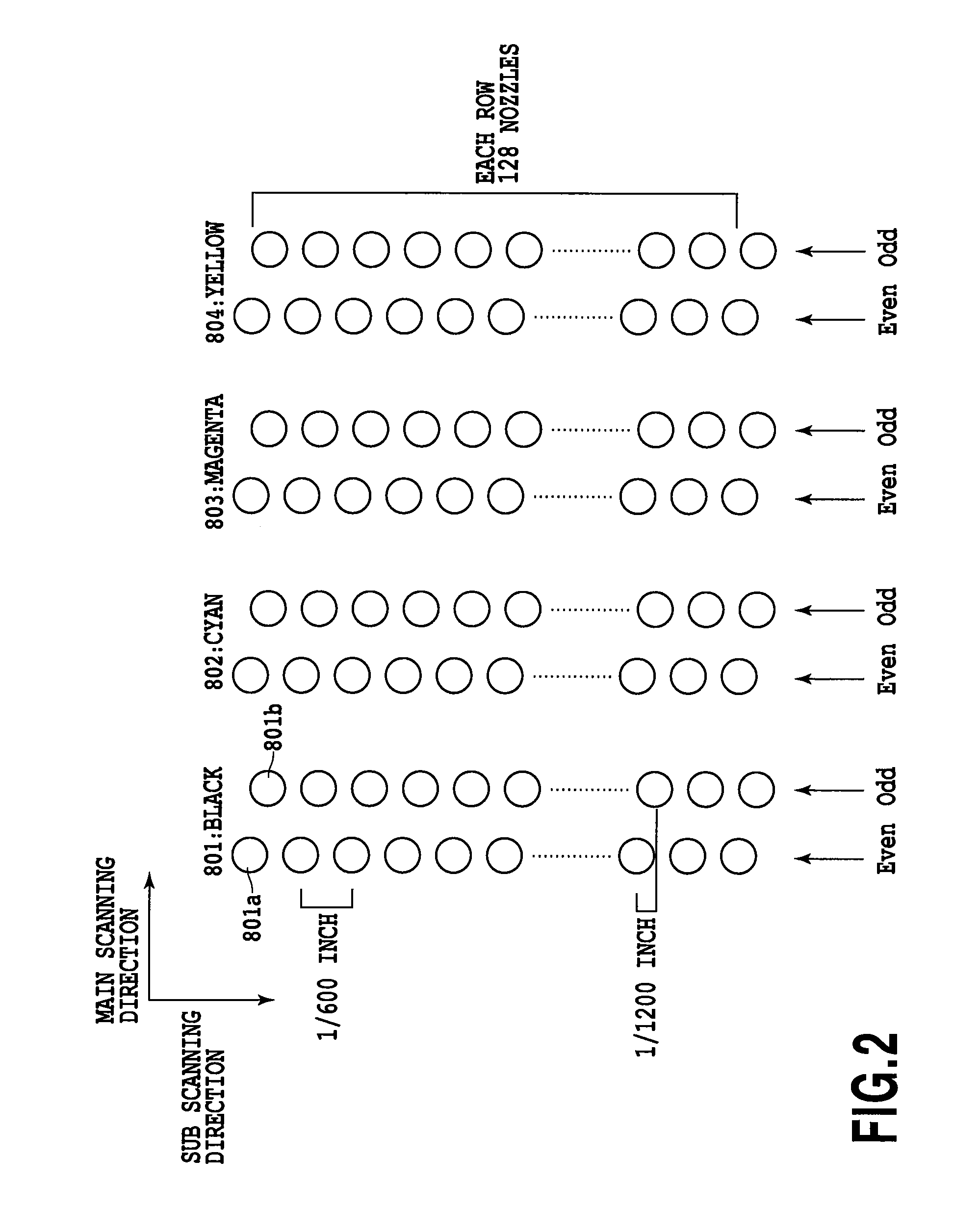
[0147]FIG. 21 is a diagram for explaining the arrangement configuration of the discharge ports (nozzles) of the printing head 201 of this embodiment. In the figure, nozzle rows 211 and 218 are nozzle rows for black ink (K), and nozzle rows 212 and 217 are nozzle rows for cyan ink (C), nozzle rows 213 and 216 are nozzle rows for magenta ink (M), and nozzle rows 214 and 215 are the nozzle rows for yellow ink (Y). This embodiment has nozzle rows every two rows of which are allocated to each color, and these eight nozzle rows are arranged so as to make a symmetrical color relationship in the main scanning direction. If with su...

third embodiment

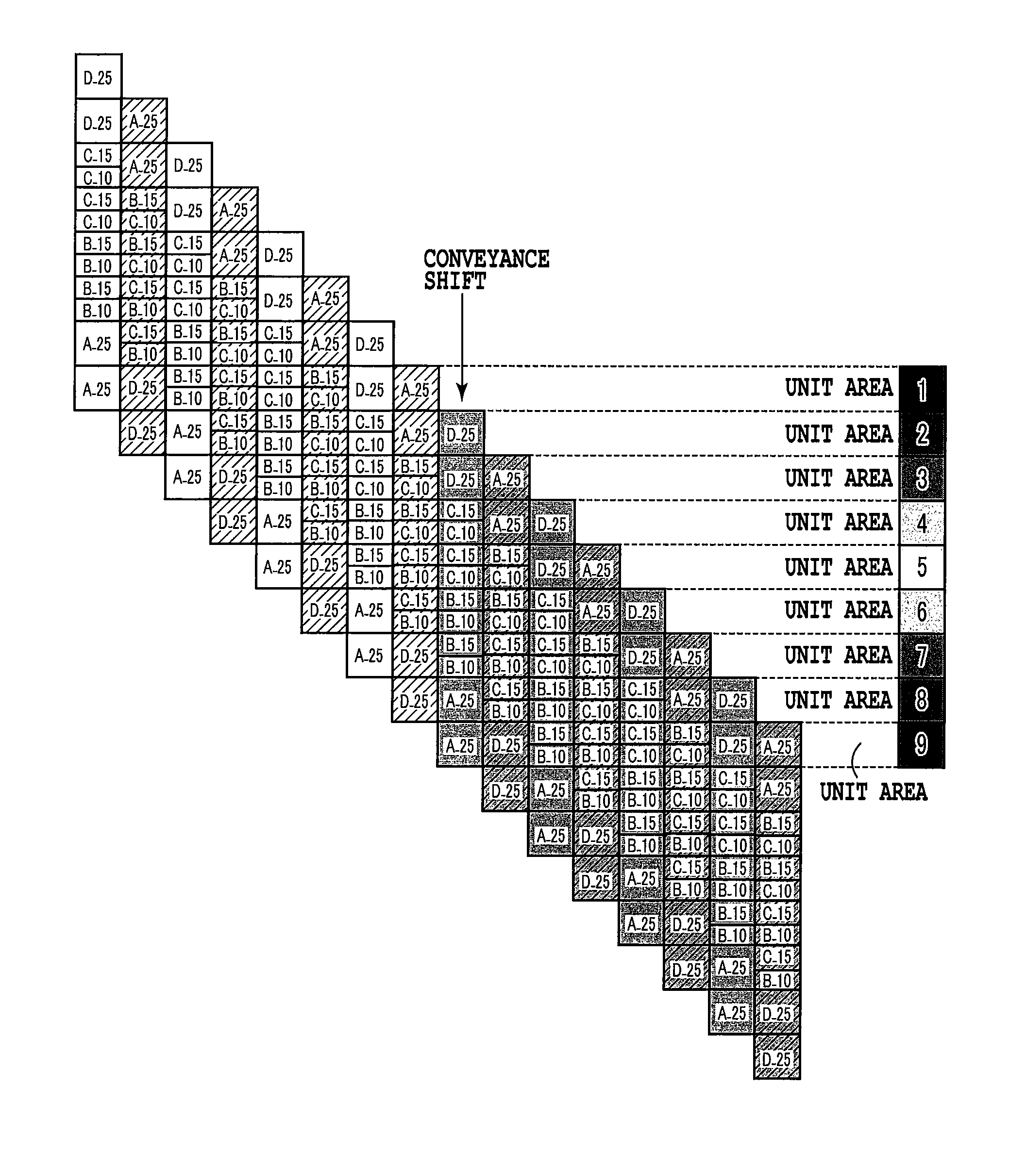
[0167]Also in this embodiment, configurations of the printing apparatus and control, a nozzle configuration of a printing head being used, a processing of the dot matrix pattern, and a storage configuration are the same as those of the second embodiment described above. However, in this embodiment, there will be given a printing method to explain a multipass printing of 16 passes that has a larger number of multipasses as a premise, the unit area where largest density reduction is anticipated with a focus given thereto, and other unit areas where the overlapped dot is separated by an appropriate quantity.

[0168]FIG. 27 is a schematic diagram for explaining the multipass printing method that is applied to this embodiment. Also here, for simplicity, explanation will be given taking masks of cyan with the nozzle rows 212 and 217, respectively, as an example. As masks of this embodiment, 16 kinds of masks A to P that each have a printable ratio of about 6.25% and are in the mutually excl...


PUM


Abstract

A printing apparatus and a printing method are capable of not permitting a printable ratio of each printing scan to have a deviation and, even if a sudden conveyance shift occurs, outputting a uniform and smooth image in the whole area of the print medium. In order to achieve this, when performing multipass printing of 2M passes, a mask such that a printable area overlapping ratio that relates to straddling between Pass M and Pass M+1 is set higher than the printable area overlapping ratio that relates to straddling between two other consecutive passes is used. By this configuration, even if a complementary relationship of dots collapses due to a sudden conveyance shift or the like and thereby a density reduction is anticipated, by an overlapped dot being separated, increase of the density is accelerated, and it becomes possible to mitigate the above-mentioned density reduction.

Description

BACKGROUND OF THE INVENTION[0001]1. Field of the Invention[0002]The present invention relates to an ink jet printing method for reducing image quality deterioration resulting from a print position shift in printing scan quantities when performing multipass printing using a serial type ink jet printing apparatus.[0003]2. Description of the Related Art[0004]As one example of the printing method using a printing head equipped with a plurality of printing elements for printing dots, there is known an ink jet printing method of printing dots on a print medium by making the printing elements discharge inks. The ink jet printing apparatus uses a printing head in which a plurality of printing elements are arranged. In the printing head, there is a case where variation arises in a discharge amount and a discharge direction among the printing elements, such variations may cause occurrence of density unevenness and stripes in an image.[0005]As a technology for mitigating such density unevennes...

Claims


Application Information

Patent Timeline
Patent Type & Authority Patents(United States)
IPC IPC(8): B41J2/205
CPCB41J2/2132G06K15/107
Inventor MURAYAMA, YOSHIAKIKONNO, YUJINISHIKORI, HITOSHIKAWATOKO, NORIHIROKANO, YUTAKA
Owner CANON KK
Why Eureka
Try Eureka