Assembly for separating a space into multiple areas

a technology for separating space and multiple areas, applied in the direction of aircraft crew accommodation, door/window protective devices, curtain suspension devices, etc., can solve the problems of increasing installation or integration effort, inability to precisely regulate the respective air conditioning state, and inability to install, etc., to achieve the effect of reducing or completely eliminating, short time and low dead weigh

Active Publication Date: 2013-12-24
AIRBUS OPERATIONS GMBH
View PDF31 Cites 6 Cited by
  • Summary
  • Abstract
  • Description
  • Claims
  • Application Information

AI Technical Summary

Benefits of technology

[0008]It is thus the object of the invention to reduce or entirely eliminate one or several of the above-mentioned disadvantages. In particular it is the object of the invention to propose an assembly for separating a space into multiple areas, which assembly makes possible installation and deinstallation if at all possible without any tools and in a relatively short time. Moreover, the assembly should to the largest extent be independent of any installations on the aircraft side and should thus not result in any excess weight in the base aircraft. Finally, for those cases where the assembly is not used it should be associated with the smallest possible stowage volume and a low dead weight.
[0009]The invention meets this object by an assembly for separating a space into multiple areas, which assembly comprises at least one frame with at least one fastening means for holding the frame in corresponding frame receiving devices, and comprises at least one foldable delimiting means, wherein the frame is designed in such a manner that in its attached state the assembly essentially conforms to one or several walls of the space, wherein the foldable delimiting means can be held to the frame and essentially prevents any airflow between adjacent areas of the space that are separated by the assembly.
[0010]By means of the assembly according to the invention, thermal separation of several areas or zones in a space is created, which separation can easily be installed and easily be removed again. The foldable delimiting means, which could, for example, be made from a textile material, some other textile-like woven material, a film or foil, a canvas or some other rollable and / or foldable material, can preferably in its folded-together state be transported in one piece into the space where it can be unfolded and suspended from the frame. The frame and the delimiting means are matched to the contours of the spaces in which the assembly according to the invention is to be used. Due to the possible use of a textile-like woven material the delimiting means can be implemented with a relatively low specific weight so that the frame does not have to absorb particularly great mass forces. Furthermore, as a result of this the inertia forces of the delimiting means are also relatively modest so that in particular a frame of the assembly according to the invention, which frame is used in a cargo compartment of an aircraft, is subjected only to relatively modest loads.

Problems solved by technology

The size of these components depends on the size of the access openings of the cargo compartment, because components that are too large cannot be conveyed into the compartment.
It is not possible to precisely regulate the respective air conditioning state in these transition areas.
If an assembly for separating a space of the design described above were used, this would require increased installation effort or integration effort that would arise immediately prior to a flight.
Within a targeted turnaround time of 90 minutes in which the aircraft is unloaded and loaded again, installation would not be possible because, during installation, activities of loading the aircraft would have to cease.
Consequently, during the installation of such an assembly for separating a space, loading of the cargo compartment in the subsequent areas cannot take place.
Pushing cargo containers through would not be possible due to the space taken up for installation.
Overall this extends the time the aircraft is tied up on the ground, thus negatively affecting the economy of the aircraft.

Method used


Image

  • Assembly for separating a space into multiple areas
  • Assembly for separating a space into multiple areas
  • Assembly for separating a space into multiple areas

Examples


Embodiment Construction

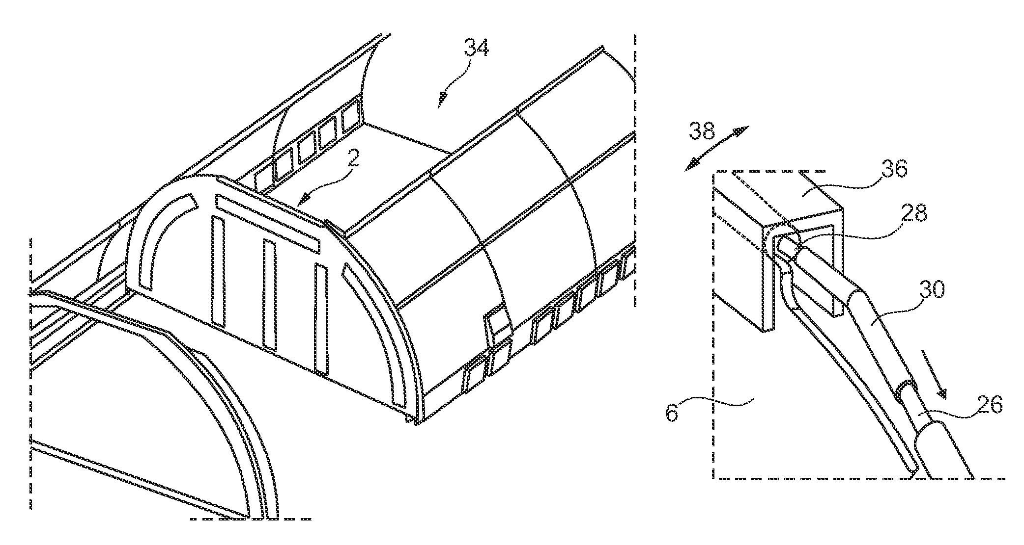
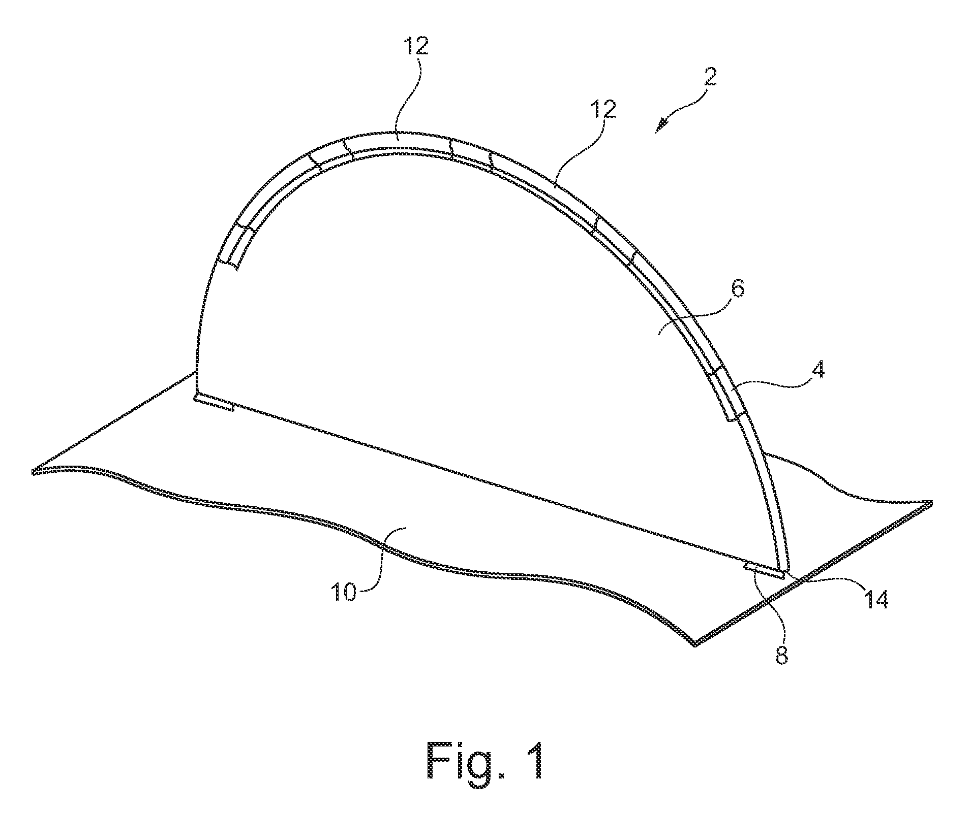
[0027]FIG. 1 shows the assembly 2 according to the invention, which comprises a frame 4, a delimiting means 6 and fastening means 8 and is situated on the floor 10 of a cargo compartment of an aircraft. The top of the assembly 2 according to the invention comprises the shape of a circular arc while the bottom is essentially straight and extends parallel to the floor 10. The fastening means 6 is designed as a canvas, a woven nylon material or some other suitable fabric that comprises several pocket-like holding devices 12 through which the frame 4 extends. At the ends of the frame 4 there are fastening means 14 that are connected to corresponding frame receiving devices which are, for example, arranged in the floor 10.

[0028]As a result of the relatively slim design of the frame 4 and its preferably elastic construction it is possible to convey the frame 4 relatively easily into the cargo compartment of an aircraft. In said compartment the frame 4 can be brought from a pre-curved shap...


PUM


Abstract

The invention relates to an arrangement for dividing a space into a plurality of areas, said arrangement comprising at least one frame with at least one fixing means for holding the frame in corresponding frame receiving elements, and at least one foldable defining means. The frame is formed in such a way that the arrangement essentially fits onto at least one wall of the space when it is fixed, the foldable defining means being able to be held on the frame and preventing an air flow between adjacent areas of the space separated by the arrangement. The arrangement according to the invention enables a thermal separation of two adjacent areas of a space, that can each be air-conditioned differently, without forming an area containing air which is a mixture from two regions at different temperatures.

Description

CROSS-REFERENCE TO RELATED APPLICATIONS[0001]This application is a National Phase entry under 35 U.S.C.§371of International Application No. PCT / EP2009 / 055875, filed May 14, 2009, published in German, which claims the benefit of the filing date of U.S. Provisional Patent Application No. 61 / 130,134 filed May 28, 2008 and of German Patent Application No. 10 2008 025 390.1 filed May 28, 2008, the entire disclosures of which are hereby incorporated herein by reference.TECHNICAL FIELD[0002]The invention relates to an assembly for separating a space into multiple areas.BACKGROUND OF THE INVENTION[0003]Assemblies for separating a space into multiple areas are well known. In the invention described below, in particular an assembly for separating a space is spotlighted more closely, which assembly can be used in a space as required, wherein said assembly to a large extent creates thermal separation between areas separated from each other, thus making it possible to maintain different spatial ...

Claims


Application Information

Patent Timeline
Patent Type & Authority Patents(United States)
IPC IPC(8): B64D11/00
CPCB64C1/10B64C1/22B64D11/0023
Inventor HARTEL, SVENWENDT, VOLKHARD
Owner AIRBUS OPERATIONS GMBH
Why Eureka
Try Eureka