Chair chassis

a chair chassis and chassis technology, applied in the field of chairs, can solve the problems of user discomfort, limited application, and user perception of the chair chassis vibration, and achieve the effects of less friction, less energy consumption, and certain resistan

Active Publication Date: 2013-12-24
HANGZHOU ZHONGTAI IND GRP
View PDF7 Cites 16 Cited by
  • Summary
  • Abstract
  • Description
  • Claims
  • Application Information

AI Technical Summary

Benefits of technology

[0003]Therefore it is a primary object of the present invention to provide a chair chassis that reduces noises caused by friction and has increased applicability for various users. Although the users have different weights, they feel the same comfort and easy operation.
[0004]It is another object of the present invention to provide a chair chassis in which the adjustment occurs with less friction and becomes easier.
[0005]It is a further object of the present invention to provide a chair chassis that provides protection against recovery force and enhances the user's comfort.
[0007]When the chair back is operated to recline and the tilting board is pressed, the middle base is still while the tilting board drives both the first pulley and the second pulley to move within the first sliding slots and the second sliding slots of the two sliding plates. And the third pulley is also sliding over the slant part of the middle base. Moreover, the lock adjustment rod is pulled to drive the locking piece that moves forward and backward and the tilting board is pressed to drive the rack that moves vertically around the shaft of the first pulley. When the locking piece is moved forward to be locked with the teeth of the rack and the device is in the lock status. When the locking piece is moved backward and is separated from the teeth of the rack to be in the unlock status. The adjustment is completed and noises generated by friction of the brake part during the reclining of the chair chassis are reduced.
[0009]The adjustment member of the chair chassis further includes an elastic part such as two-arm torsion spring. One end of the elastic part is connected to the lock adjustment rod while the other end thereof is connected to the locking piece. Thus the elastic part driven by the pulled lock adjustment rod drives the locking piece to move forward or backward. By the elastic part, the adjustment is with less friction and more energy-saving.
[0010]The chair chassis further includes a partition, a cover plate and a block disposed on an inner side of the slant part of the middle base. A through hole for the locking piece moving forward / backward therein is mounted on the partition. The cover plate and the block are respectively arranged above and under the locking piece for receiving the locking piece. The partition is further fixed with an elastic pad having a concave-convex surface that is leaning against by the lock adjustment rod. While being pulled, the lock adjustment rod leans against the concave-convex surface of the elastic pad and moves thereon so as to have certain resistance during the locking and unlocking processes of the lock adjustment rod. Thus the chair chassis is not turned back to the original position immediately when the locking piece is released from the lock status. That means the locking piece and the rack are not separated immediately and a certain force is required to apply to the chair back for separating the locking piece and the rack. Thus a protection for turning back of the locking piece is provided to enhance users' comfort.

Problems solved by technology

Thus the applicability is limited.
Moreover, while reclining the chair back, noises are created due to friction of a brake part.
And once the chair back is turned back quickly, users sense the vibration of the chair chassis and feel uncomfortable.

Method used


Image

  • Chair chassis
  • Chair chassis
  • Chair chassis

Examples


Embodiment Construction

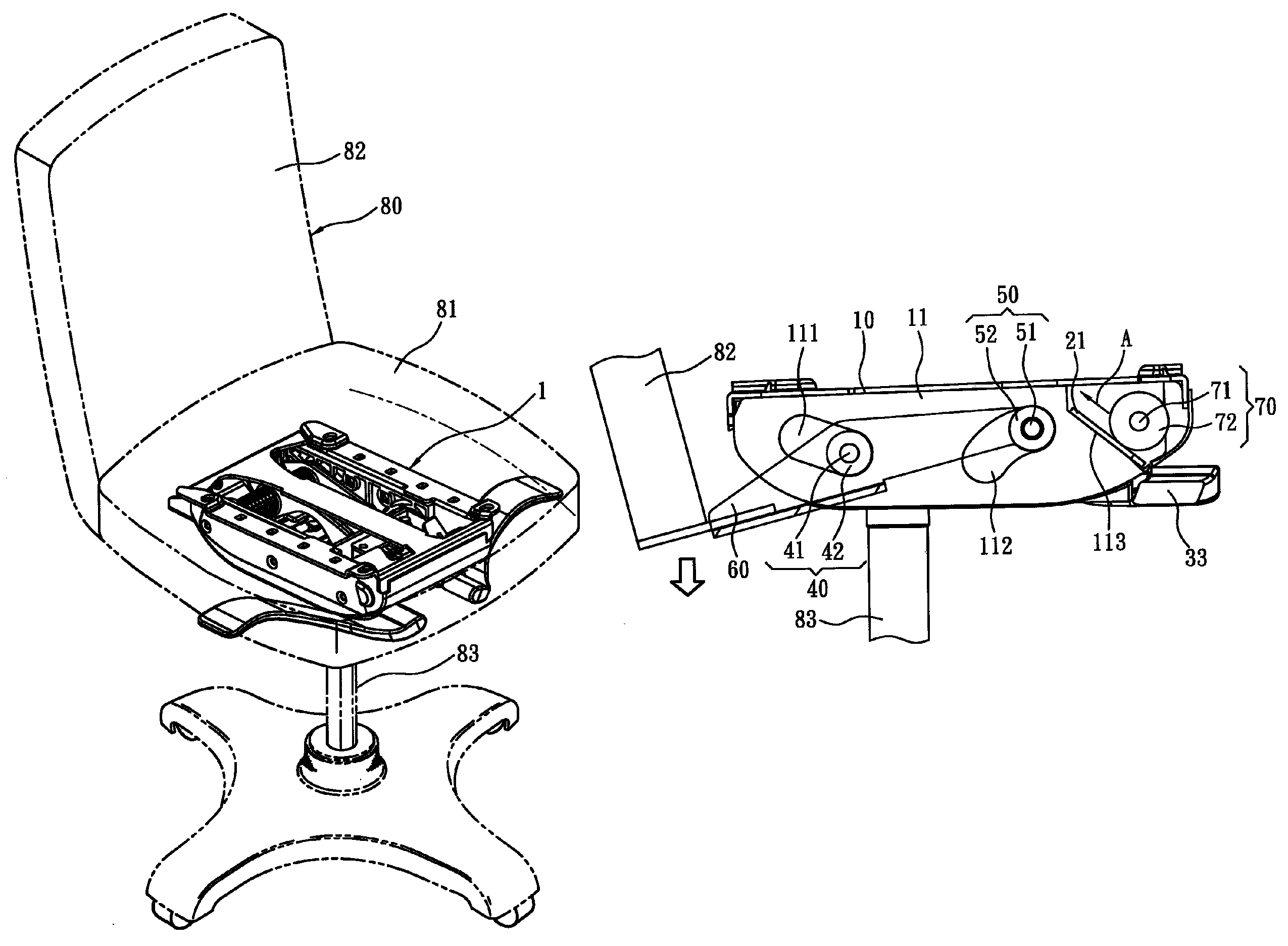
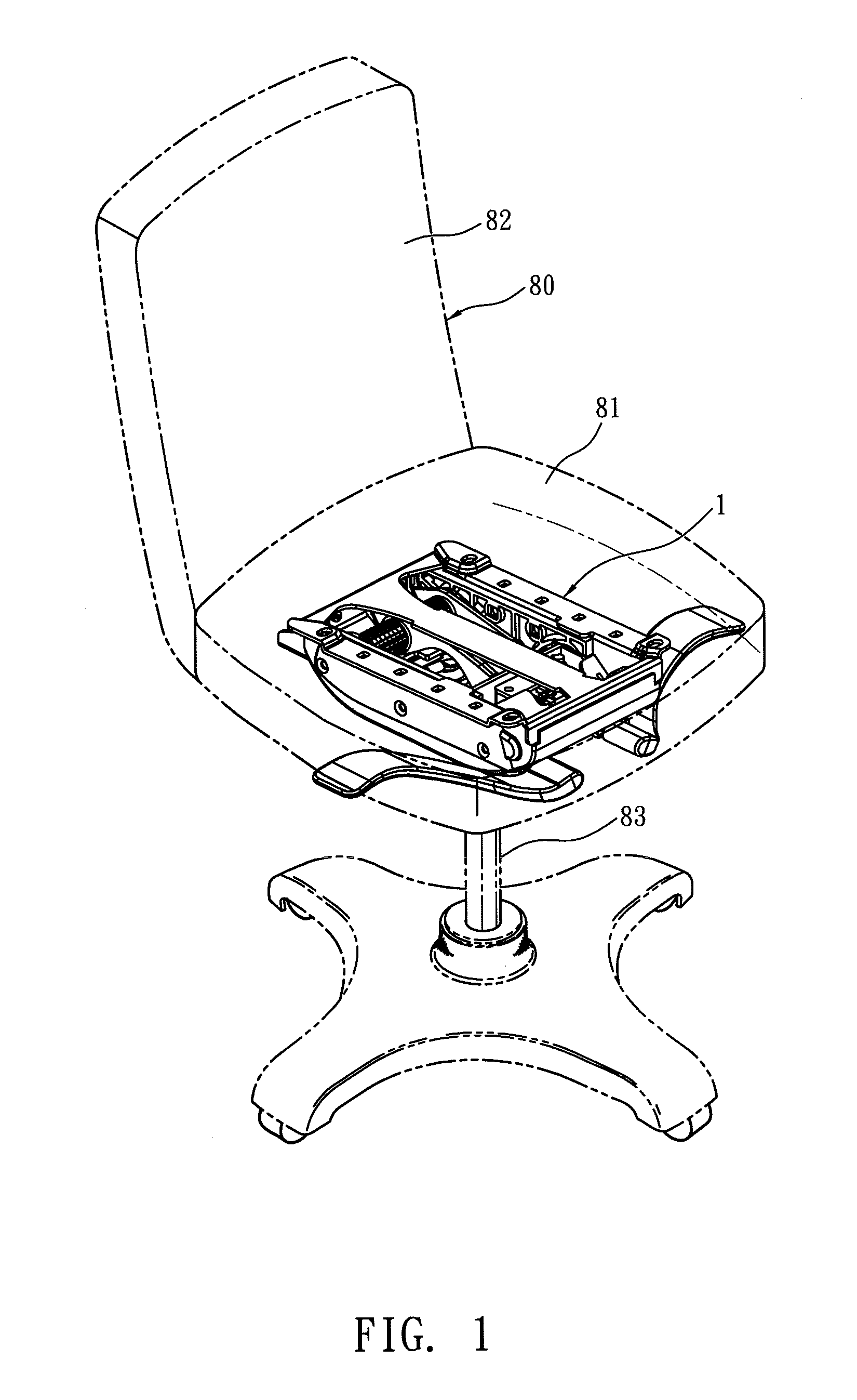
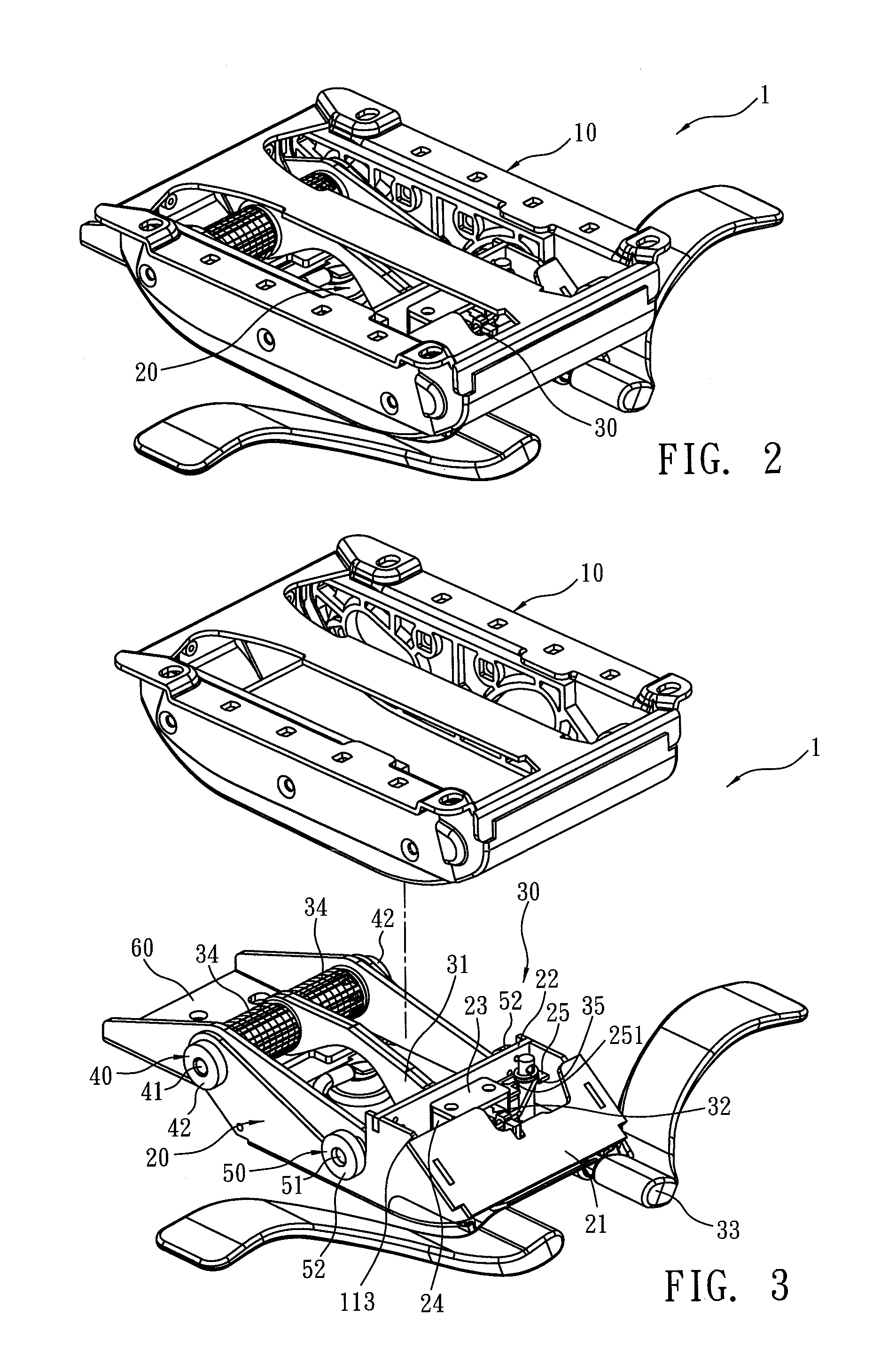
[0021]Refer from FIG. 1 and FIG. 2, a chair chassis 1 of the present invention includes a seat base 10, a middle base 20 and an adjustment member 30. The seat base is fixed on a bottom of a seat 81 of a chair 80. As shown in FIG. 7, a sliding plate 11 is connected to the left side and the right side of the seat base 10 respectively. A first sliding slot 111 inclined is arranged at a front end 11a of the sliding plate 11 and a second sliding slot 112 declined is disposed on a rear end 11b of the sliding plate 11. The first sliding slots 111 of the two sliding plate 11 are arranged symmetrical and so are the second sliding slots 112. A first pulley 40 is disposed between the two first sliding slots 111. The first pulley 40 consists of a shaft 41 and two wheels 42 that are respectively connected to each of two ends of the shaft 41 and mounted in each first sliding slot 111. Similarly, a second pulley 50 is set between the two second sliding slots 112. The second pulley 50 is composed o...


PUM


Abstract

A chair chassis is revealed. The chair chassis includes a seat base, a middle base and an adjustment member. A sliding plate is connected to each side of the seat base. A sliding slot is arranged at a front and a rear end of each sliding plate and a pulley is arranged transversely between two sliding slots. The two pulleys connect to a tilting board. The middle base between the two sliding plates connects to the tilting board and the two sliding plates by the pulley on the front end. A third pulley slides over a slant part of the middle base. The adjustment member includes a rack, a locking piece and a lock adjustment rod for control of movement of the locking piece to be engaged with and separated from the rack. Thus users with various weights can use the same chair chassis and operate the chair chassis easier.

Description

BACKGROUND OF THE INVENTION[0001]The present invention relates to a chassis, especially to a chair chassis for offering users with different weights comfort and reducing vibration and abrasion while reclining chair backs of chairs.[0002]Generally, a chair chassis includes a plurality of components such as an upper support tray, a lower support rod, a shaft, springs, etc. The upper support tray is fixed with and connected to a chair back so that the chair back is adjusted and reclined to different angles around the shaft. Thus the chair with adjustable recline angles makes users feel more comfortable and relaxed. Refer to Chinese Pat. CN 2587252Y, a support tray for chairs revealed includes a torsion spring so as to adjust the chair back. For users with different weights, various torsion springs are required. Thus the applicability is limited. Moreover, while reclining the chair back, noises are created due to friction of a brake part. And once the chair back is turned back quickly, ...

Claims


Application Information

Patent Timeline
Patent Type & Authority Patents(United States)
IPC IPC(8): A47C1/024
CPCA47C1/026
Inventor NI, YONG-XING
Owner HANGZHOU ZHONGTAI IND GRP
Why Eureka
Try Eureka