Preload device of ball bearing and motor having the preload device

a technology of preload device and ball bearing, which is applied in the direction of machine supports, wound springs, other domestic objects, etc., can solve the problems of large ball play, weak bearing stiffness, increased rotational vibration of the shaft, etc., and achieves the effect of convenient handling

Active Publication Date: 2013-12-24
MINEBEAMITSUMI INC
View PDF9 Cites 4 Cited by
  • Summary
  • Abstract
  • Description
  • Claims
  • Application Information

AI Technical Summary

Benefits of technology

[0008]The present invention has been made in view of the above circumstances, and it is an aspect of the present invention to provide a preload device of a ball bearing which allows a preload spring to be easily handled and appropriately applies preload to the ball bearing and a motor having the preload device.
[0011]According to the above configuration, it is possible to provide a preload device of a ball bearing which allows a preload spring to be easily handled and appropriately applies preload to the ball bearing.

Problems solved by technology

When a ball bearing is used as a bearing of a rotational shaft of a motor and the like, if an internal clearance in the bearing exists, a play of a ball is large and stiffness of the bearing is weak.
As a result, the rotational vibration of the shaft is increased.
In addition, when assembling the rotational shaft and the ball bearing, it is difficult to perform the assembling because the ball bearing is pressed and thus returned due to the elastic force of the coil spring returning to its free length.
However, when the bearing device is provided in a cylinder, it is not possible to release the lock state, and therefore, the elastic force of the coil spring is still an obstacle in assembling the shaft and the bearing.
Further, since the coil spring is enclosed in the inner and outer cylinders, it is not possible to recognize whether or not the coil spring is provided or a type of the coil spring at a later time, so that it is not possible to appropriately apply the preload.

Method used


Image

  • Preload device of ball bearing and motor having the preload device
  • Preload device of ball bearing and motor having the preload device
  • Preload device of ball bearing and motor having the preload device

Examples


Embodiment Construction

[0021]Hereinafter, illustrative embodiments of the present invention will be described with reference to the drawings.

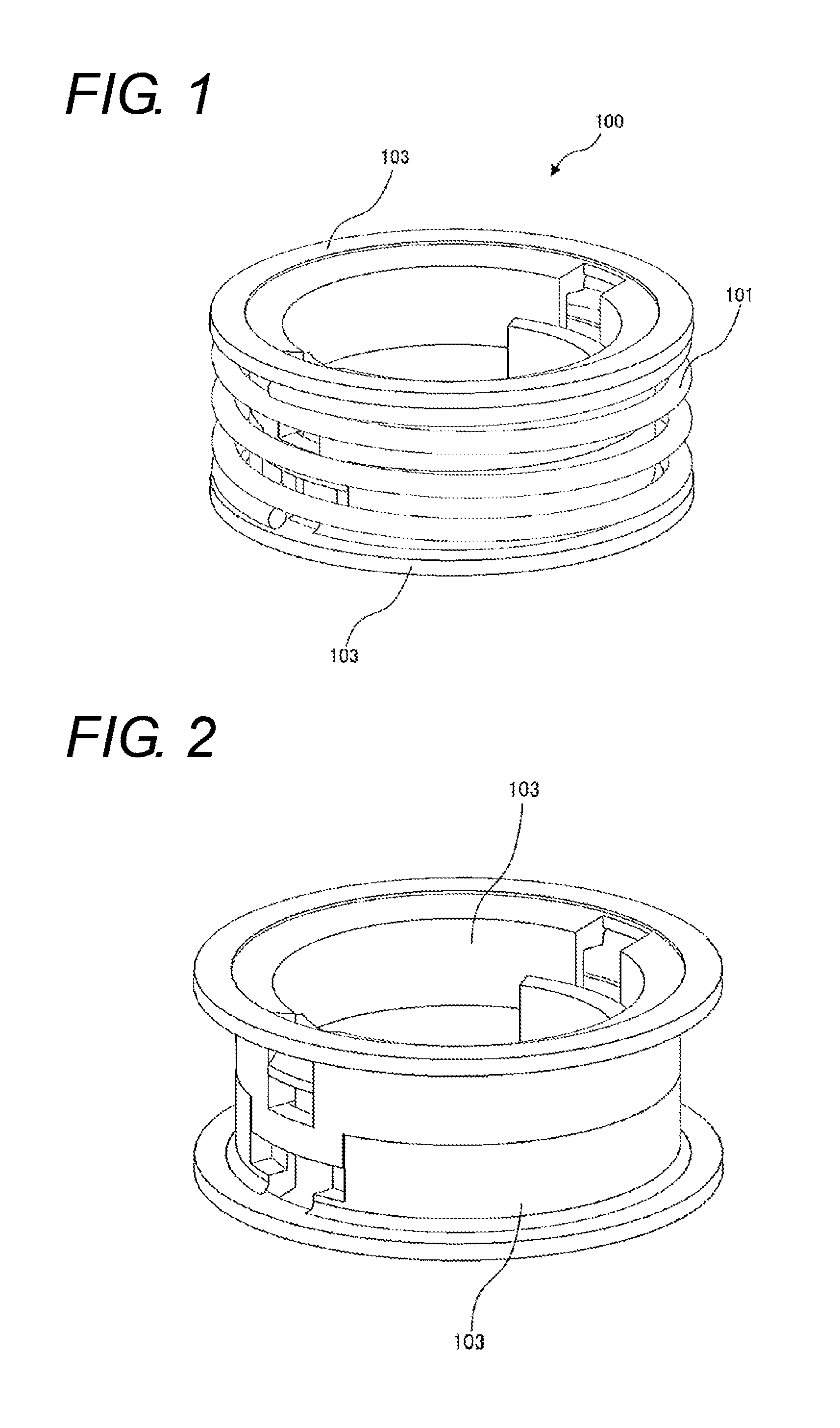
[0022]FIG. 1 is a perspective view showing a preload device that is used to apply preload to a ball bearing according to an illustrative embodiment of the present invention.

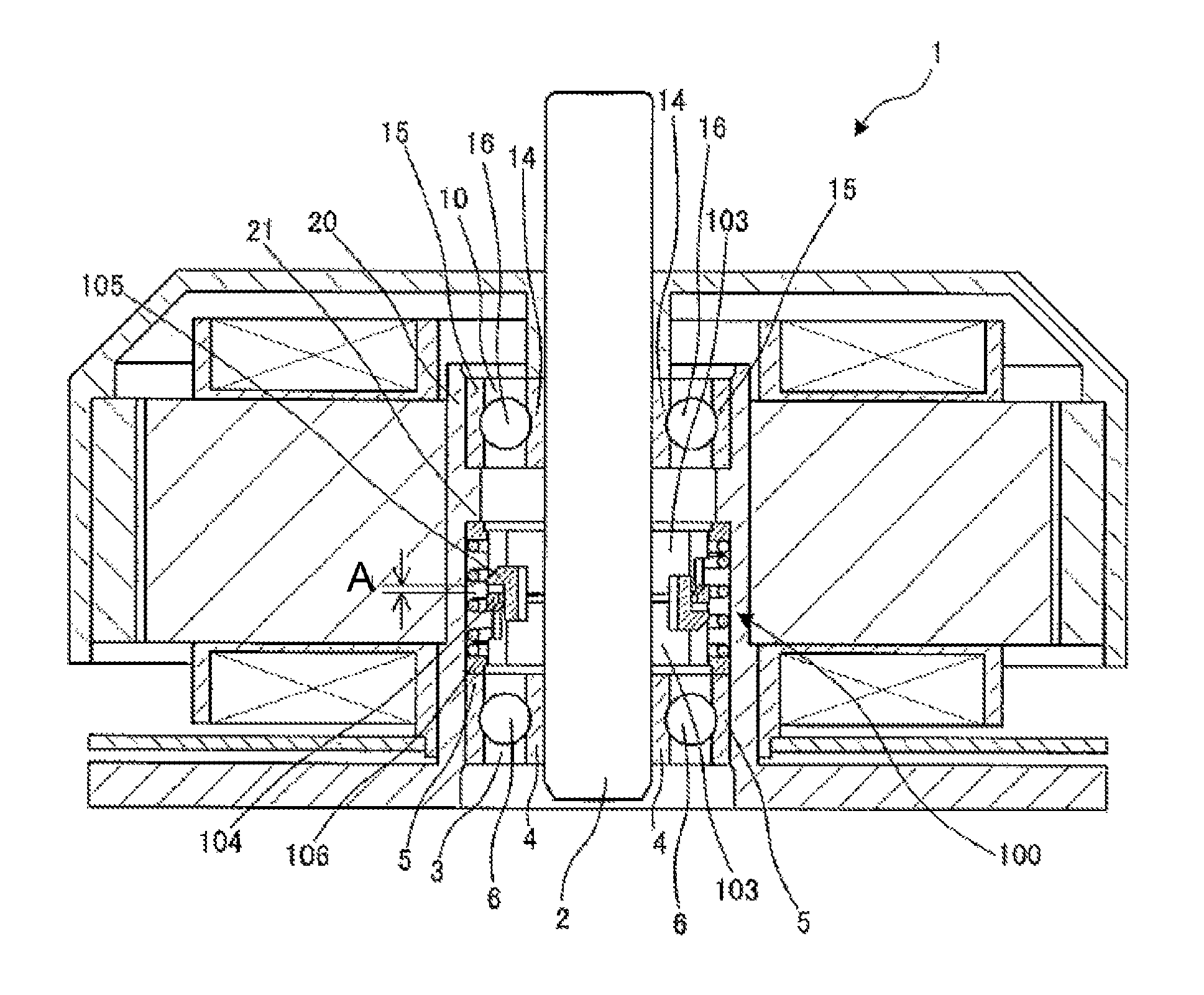
[0023]A preload device 100 includes a coil spring 101 that is an elastic member for preload and is held between upper and lower holders 103. The upper and lower holders 103 are engaged to each other, so that the coil spring 101 is held at an urging state.

[0024]In this illustrative embodiment, the coil spring 101 is used as an elastic member for preload. However, the present invention is not limited thereto. For example, a cylindrical rubber member may be used as an elastic member for preload.

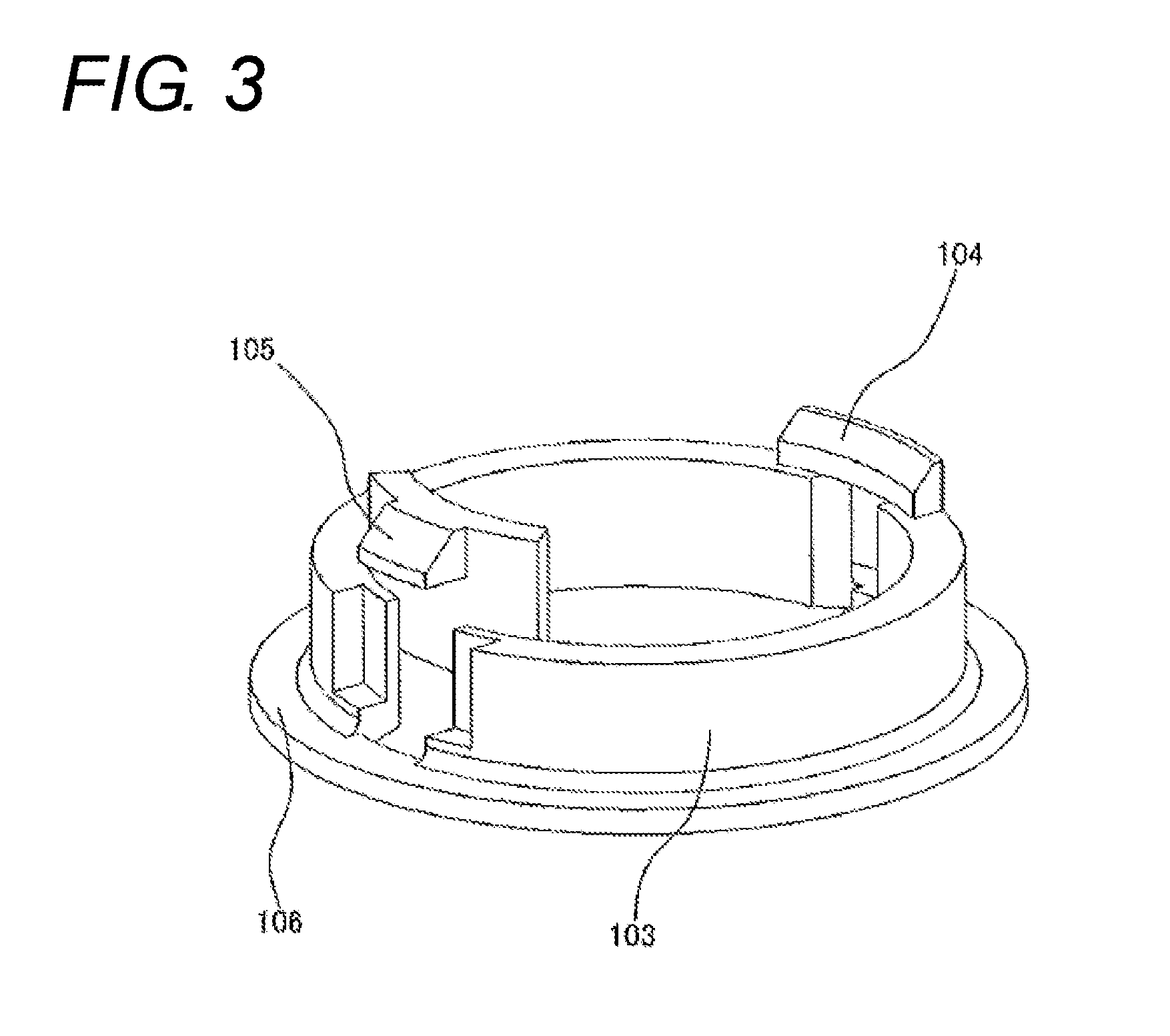
[0025]FIG. 2 is a perspective view in which the coil spring 101 is removed from the preload device 100 shown in FIG. 1. FIG. 3 is a perspective view showing one of the holders 103.

[0026]In this illustrative em...


PUM


Abstract

A constant preload device of a ball bearing is provided. The preload device includes an elastic member having a hollow shape with openings at both sides in an elastic direction, and two holders inserted into the openings at the both sides of the elastic member, respectively. Each holder includes a flange part configured to contact an end portion of the opening, into which the holder is inserted, to regulate an extension of the elastic member in the elastic direction, and a claw part configured to engage with the other holder to regulate separation from the other holder. The holders are engaged to each other by the claw parts such that the elastic member is exposed from the holders. When the preload device applies preload to the ball bearing, the ball bearing contacts the preload device only at an outer ring of the ball bearing.

Description

BACKGROUND OF THE INVENTION[0001]1. Field of the Invention[0002]The present invention relates to a preload device of a ball bearing by a coil spring and a motor having the preload device.[0003]2. Description of the Related Art[0004]When a ball bearing is used as a bearing of a rotational shaft of a motor and the like, if an internal clearance in the bearing exists, a play of a ball is large and stiffness of the bearing is weak. As a result, the rotational vibration of the shaft is increased. Therefore, a preload structure has been known which applies preload to the bearing so as to decrease the play of the ball.[0005]For example, JP-UM-A-H4-82425 describes a preload structure where an outer ring is mounted to a rolling groove provided to a shaft via rolling elements, and preload is applied to the outer ring in an axial direction, thereby reducing the play of the rolling elements.[0006]In such preload structure of applying the preload to the ball bearing, elastic force of a coil spri...

Claims


Application Information

Patent Timeline
Patent Type & Authority Patents(United States)
IPC IPC(8): F16C33/66F16M13/00F16C43/00F16F1/12
CPCF16C19/06F16C25/083F16C2380/26
Inventor TAKAHASHI, YUUKISUZUKI, YUZURU
Owner MINEBEAMITSUMI INC
Why Eureka
Try Eureka