High linear voltage variable attenuator (VVA)

a voltage variable attenuator and high linear technology, applied in the field of communication circuits, can solve the problems of compromising the ultimate performance of conventional vvas, limited techniques, etc., and achieve the effects of high linear output, low insertion loss, and high power handling

Active Publication Date: 2013-12-24
MACOM TECH SOLUTIONS HLDG INC
View PDF4 Cites 16 Cited by
  • Summary
  • Abstract
  • Description
  • Claims
  • Application Information

AI Technical Summary

Benefits of technology

[0005]The objects, features and advantages of the present invention include implementing a voltage variable attenuator (VVA) that may (i) provide a highly linear output, (ii) implement high power handling, (iii) have low insertion loss and VSWR, (iv) have a low power consumption configuration, (v) comprise low control voltage, (vi) be optimized for system, size and / or cost requirements and / or (vii) be easily implemented.

Problems solved by technology

Very frequently, however, this technique is limited by the particular process technology implemented.
Certain process technologies only offer a limited number of gates per transistor, thus compromising the ultimate performance of conventional VVAs.

Method used


Image

  • High linear voltage variable attenuator (VVA)
  • High linear voltage variable attenuator (VVA)
  • High linear voltage variable attenuator (VVA)

Examples


Embodiment Construction

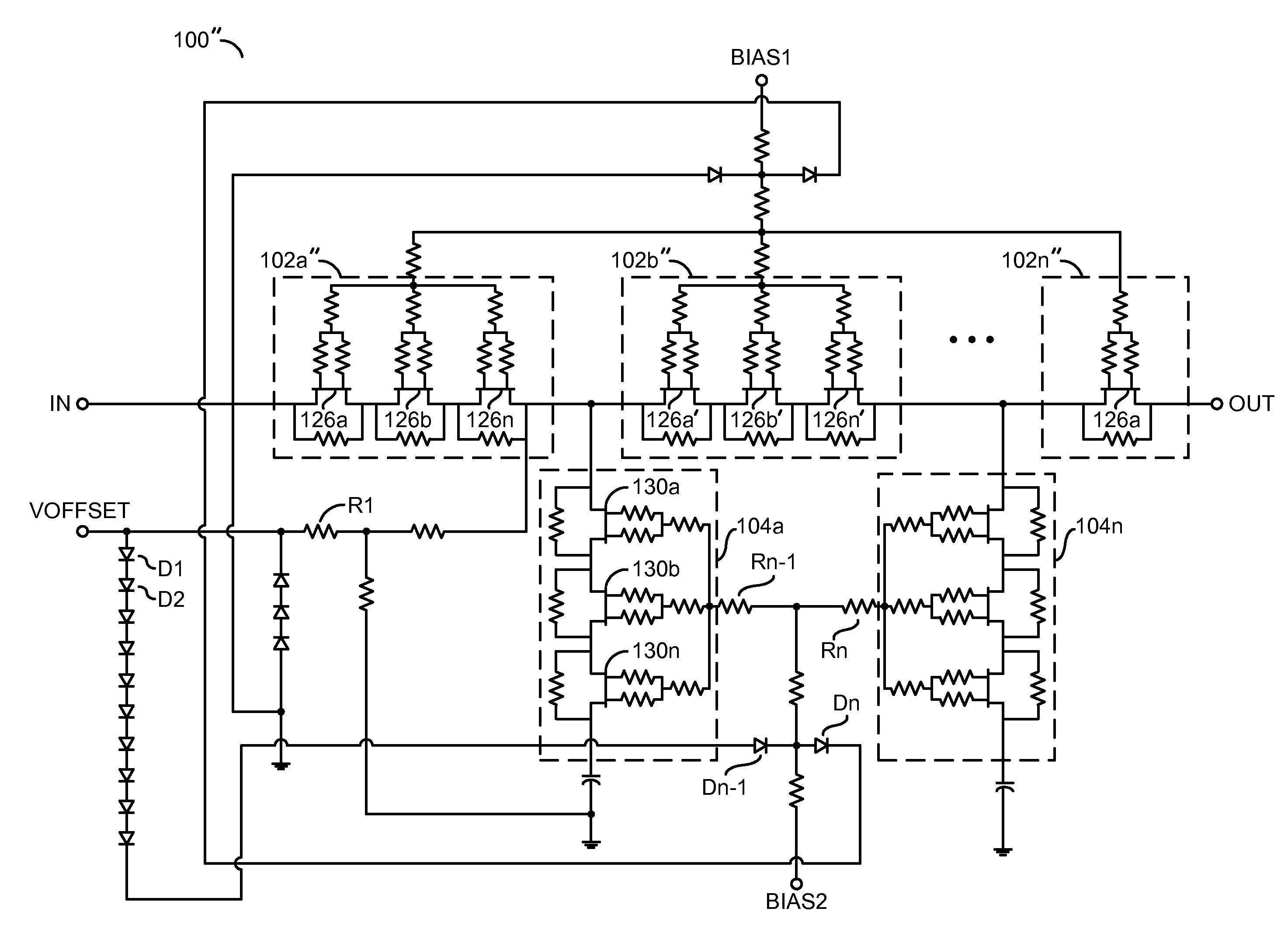
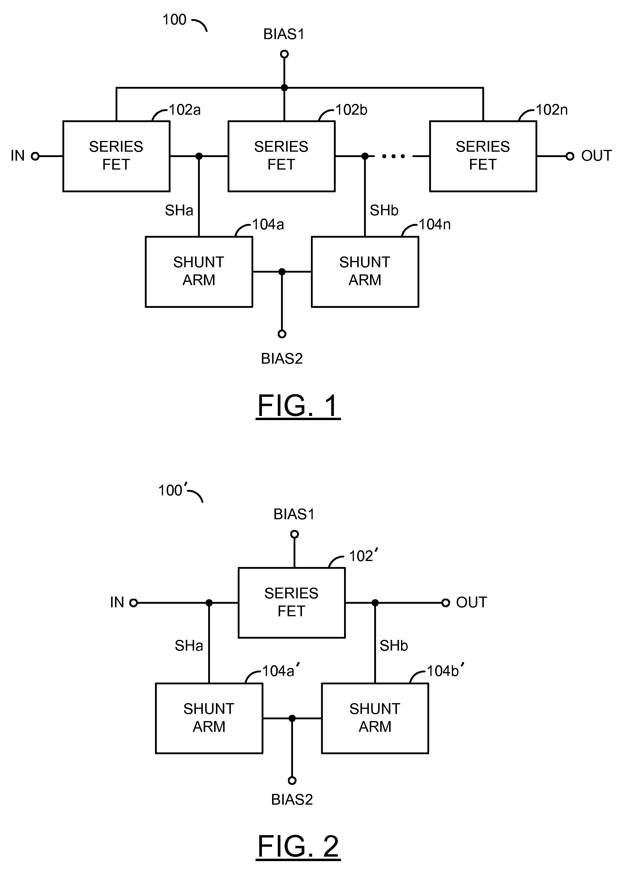
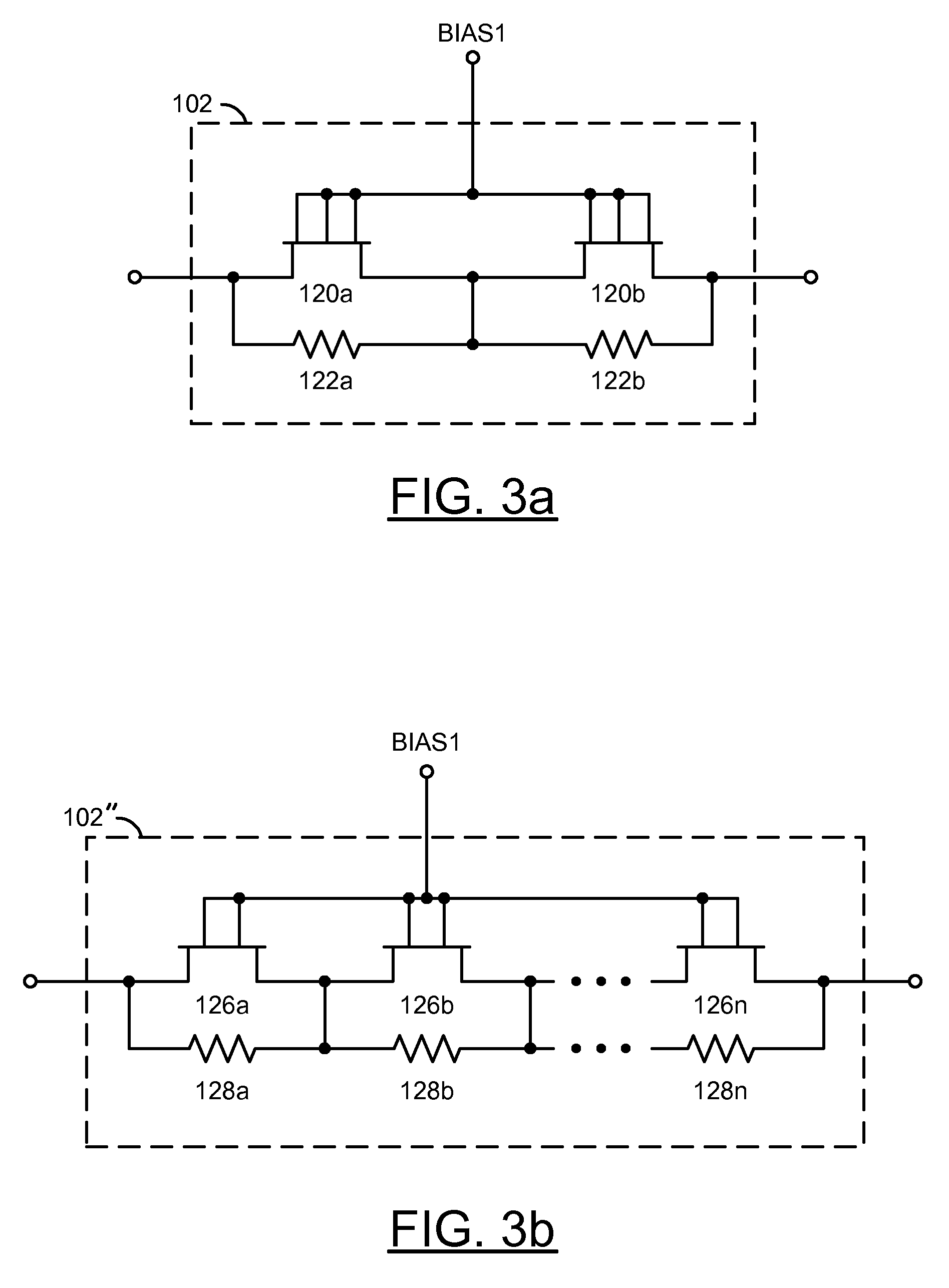
[0017]Referring to FIG. 1, a block diagram of a system 100 is shown in accordance with a preferred embodiment of the present invention. The system 100 may be implemented as a Voltage Variable Attenuator (VVA). The system 100 illustrates a T configuration. The system 100 generally comprises a plurality of blocks (or circuits) 102a-102n and a plurality of blocks (or circuits) 104a-104n. The blocks 102a-102n may be implemented as series field-effect transistor (FET) circuits. The blocks 102a-102n may collectively comprise a network of series transistor elements (or a series transistor network). The blocks 104a-104n may be implemented as shunt arm circuits. The blocks 102a-102n may each comprise a number of transistors and a number of resistors (to be described in connection with FIGS. 3a-b). The blocks 104a-104b may each comprise a number of transistors (to be described in connection with FIGS. 4a-b).

[0018]In one example, the system 100 may comprise a series FET circuit 102a, a series ...


PUM


Abstract

An apparatus comprising one or more series transistor network elements and a plurality of shunt circuits. The series transistor network may be configured to generate an output signal in response to (i) an input signal, (ii) a first bias signal, and (iii) a plurality of variable impedances. The plurality of shunt circuits may each be configured to generate a respective one of the variable impedances in response to a second bias signal. The output signal may have an attenuation that is equal to or less than the input power. The amount of the attenuation may be controlled by the first bias signal and the second bias signal. The series transistor elements and the plurality of shunt circuits may be configured as two or more transistors each having two or more gates.

Description

FIELD OF THE INVENTION[0001]The present invention relates to communication circuits generally and, more particularly, to a method and / or apparatus for implementing a high linear voltage variable attenuator (VVA).BACKGROUND OF THE INVENTION[0002]T or Pi topologies are used in conventional Voltage Variable Attenuators (VVAs). Linearity is determined by each arm of the VVA. Designers often use multi-gate MESFETs or pHEMTs in each arm to improve the power handling and linearity performance. Very frequently, however, this technique is limited by the particular process technology implemented. Certain process technologies only offer a limited number of gates per transistor, thus compromising the ultimate performance of conventional VVAs.[0003]It would be desirable to implement a voltage variable attenuator (VVA) having high linearity using known process technologies.SUMMARY OF THE INVENTION[0004]The present invention concerns an apparatus comprising a one or more series transistor elements...

Claims


Application Information

Patent Timeline
Patent Type & Authority Patents(United States)
IPC IPC(8): H03L5/00
CPCH03H11/245
Inventor ZHANG, WEN HUI
Owner MACOM TECH SOLUTIONS HLDG INC
Why Eureka
Try Eureka