Solid-state lamps with improved radial emission and thermal performance

a technology of solid-state lamps and radial emission, which is applied in the direction of discharge tube luminescnet screens, lighting and heating apparatus, lighting support devices, etc., can solve the problems of inefficiency of traditional incandescent light bulbs, life time problems, and the difficulty of known led-based lamps matching the functionality and form factor of incandescent bulbs, so as to achieve the effect of improving emission and thermal characteristics

Inactive Publication Date: 2013-12-31
INTEMATIX
View PDF187 Cites 32 Cited by
  • Summary
  • Abstract
  • Description
  • Claims
  • Application Information

AI Technical Summary

Benefits of technology

[0011]In an embodiment of the invention a lamp, comprises at least one solid-state light emitting device; a thermally conductive body; at least one duct; and a photoluminescence wavelength conversion component remote to the at least one solid state light emitting device, wherein the at least one duct extends through the photoluminescence wavelength conversion component. The duct which can be formed as an integral part of the body or as a separate component is configured to define a pathway for thermal airflow through the thermally conductive body and thereby provide cooling of the body and the at least one light emitting device.
[0017]Typically photoluminescence materials such as phosphors have a yellow to orange appearance and to improve the visual appearance of the component in an off-state the component can further comprise a light diffusive layer on the component. Such light diffusive materials which can include titanium dioxide (TiO2), barium sulfate (BaSO4), magnesium oxide (MgO), silicon dioxide (SiO2) or aluminum oxide (Al2O3) preferably have a white appearance thereby lessening the yellow appearance of the component in the off-state.
[0022]The lamp can further comprise a light diffusive component. In some embodiments the light diffusive component in conjunction with the light reflective surface and the end surface of the body defines a volume enclosing the at least one light emitting device. The light diffusive component preferably comprises a toroidal shell. For ease of fabrication and to eliminate the need for a collapsible former during molding of the component, the toroidal shell can comprise two parts that are identical.

Problems solved by technology

Traditional incandescent light bulbs are inefficient and have life time issues.
However the known LED-based lamps typically have difficulty matching the functionality and form factor of incandescent bulbs.

Method used


Image

  • Solid-state lamps with improved radial emission and thermal performance
  • Solid-state lamps with improved radial emission and thermal performance
  • Solid-state lamps with improved radial emission and thermal performance

Examples


Embodiment Construction

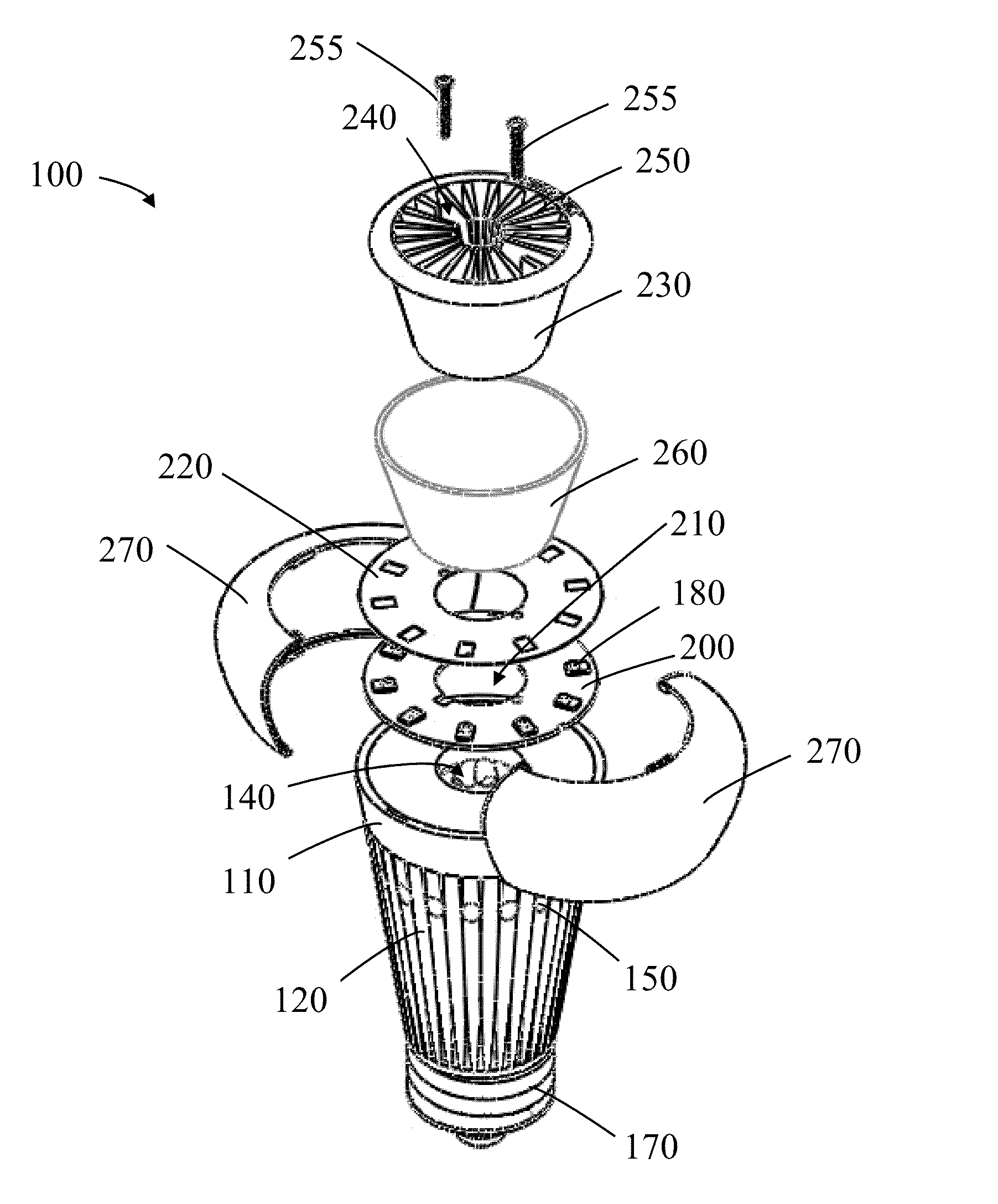
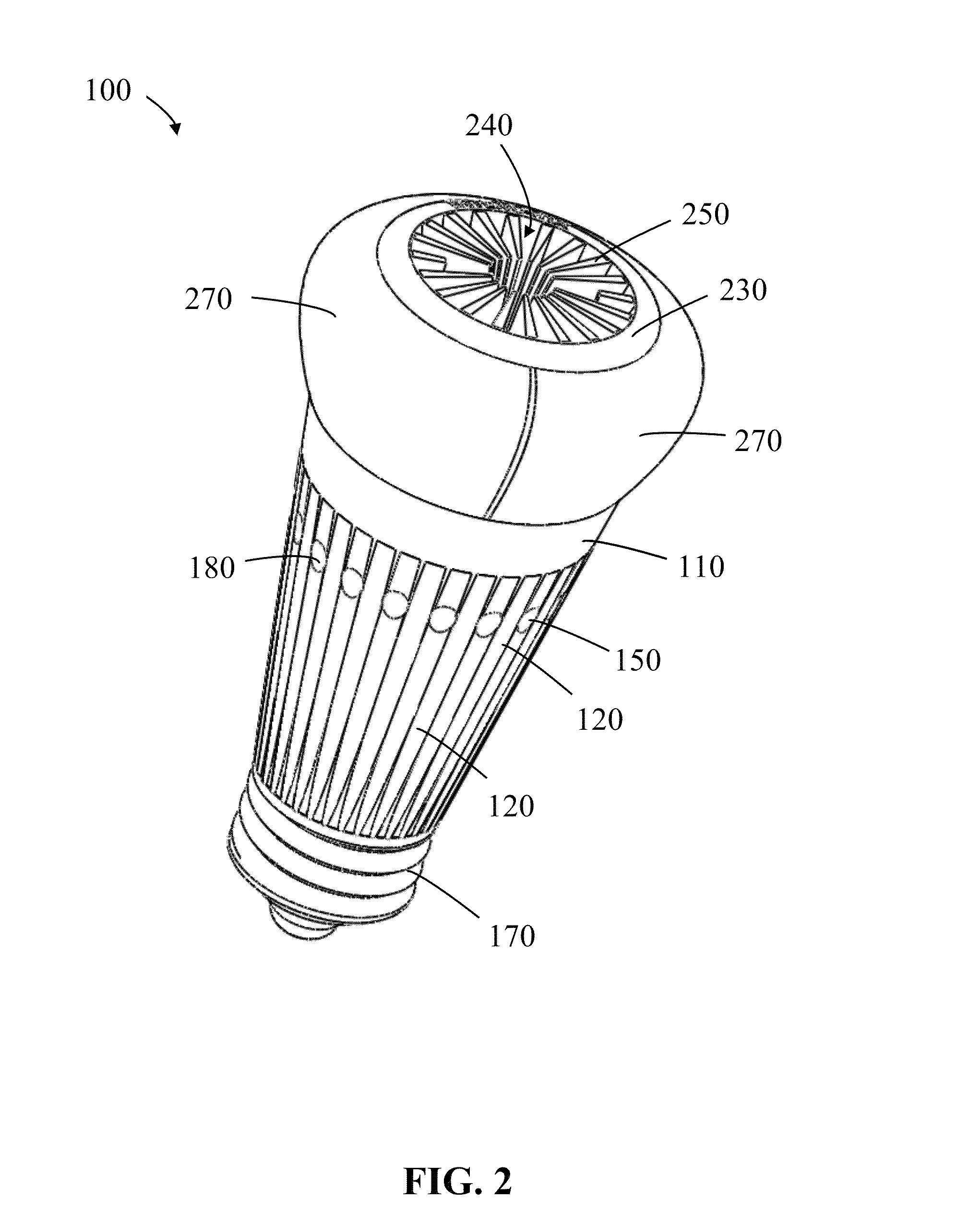
[0046]Throughout this patent specification like reference numerals are used to denote like parts.

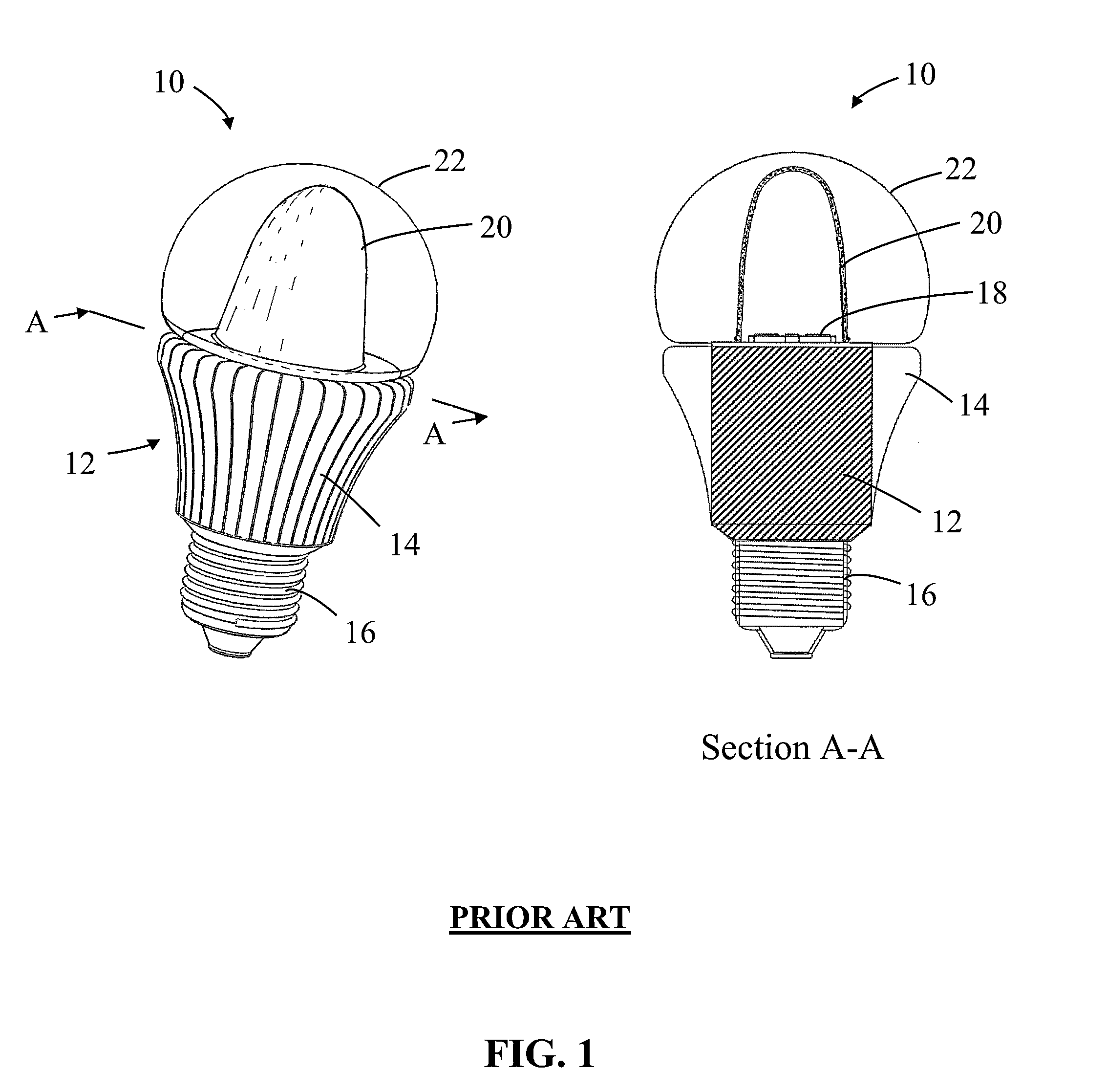
[0047]Lamps (light bulbs) are available in a number of forms, and are often standardly referenced by a combination of letters and numbers. The letter designation of a lamp typically refers to the particular shape of type of that lamp, such as General Service (A, mushroom), High Wattage General Service (PS—pear shaped), Decorative (B—candle, CA—twisted candle, BA—bent-tip candle, F—flame, P—fancy round, G—globe), Reflector (R), Parabolic aluminized reflector (PAR) and Multifaceted reflector (MR). The number designation refers to the size of a lamp, often by indicating the diameter of a lamp in units of eighths of an inch. Thus, an A-19 type lamp refers to a general service lamp (bulb) whose shape is referred to by the letter “A” and has a maximum diameter two and three eights of an inch. As of the time of filing of this patent document, the most commonly used household “light bulb” is the...


PUM

PropertyMeasurementUnit
luminous efficacyaaaaaaaaaa
lengthaaaaaaaaaa
temperatureaaaaaaaaaa

Abstract

A solid-state lamp comprises: one or more solid-state light emitting devices (typically LEDs); a thermally conductive body; at least one duct; and a photoluminescence wavelength conversion component remote to the one or more LEDs. The lamp is configured such that the duct extends through the photoluminescence wavelength conversion component and defines a pathway for thermal airflow through the thermally conductive body to thereby provide cooling of the body and the one or more LEDs.

Description

CROSS-REFERENCES TO RELATED APPLICATIONS[0001]This application is a continuation of U.S. application Ser. No. 13 / 411,497 filed on Mar. 2, 2012 entitled “Solid-State Lamps with Improved Radial Emission and Thermal Performance”, which claims the benefit of priority to U.S. Provisional Application No. 61 / 544,272 filed on Oct. 6, 2011 entitled “Solid-State Light Sources With Improved Radial Emission and Thermal Performance” and to U.S. Provisional Application No. 61 / 568,138 filed on Dec. 7, 2011 entitled “Solid-State Light Sources with Improved Radial Emission and Thermal Performance”, the contents of which applications are incorporated herein by reference in their entireties.BACKGROUND OF THE INVENTION[0002]1. Field of the Invention[0003]Embodiments of the invention relate to solid-state lamps with improved radial emission and thermal performance. In particular, although not exclusively, embodiments concern LED-based (Light Emitting Diode) lamps with an omnidirectional emission pattern...

Claims


Application Information

Patent Timeline
Patent Type & Authority Patents(United States)
IPC IPC(8): F21V29/02F21V9/16F21V9/40
CPCF21K9/50F21V3/02F21K9/13F21V29/2231F21V13/12F21V7/20F21K9/56F21V29/2293F21V29/262F21Y2101/02F21V7/041F21V29/505F21V29/713F21V29/773F21V29/83F21K9/23F21K9/60F21K9/64F21Y2115/10
Inventor LEE, HYUNG-CHULYANG, HAITAOEDWARDS, CHARLESLI, YI-QUN
Owner INTEMATIX
Why Eureka
Try Eureka