Identification and simulation of multiple subgraphs in multi-domain graphical modeling environment

a multi-domain, graphical modeling environment technology, applied in the direction of process and machine control, program control, instruments, etc., can solve the problems of event calendar, data delay and other data consistency problems, existing techniques that do not support interleaved execution of multi-domain components of hybrid discrete event system models,

Active Publication Date: 2013-12-31
THE MATHWORKS INC
View PDF7 Cites 33 Cited by
  • Summary
  • Abstract
  • Description
  • Claims
  • Application Information

AI Technical Summary

Problems solved by technology

However, many models require the execution of some time-driven components in between the execution of event-driven components.
Existing techniques do not support interleaved execution of multi-domain components of a hybrid Discrete Event System model.
This paradigm for modeling and simulation introduced data delays and other data consistency problems at the interaction of the two domains as defined by the signal lines.
An additional problem that occurs with grouping all the...

Method used


Image

  • Identification and simulation of multiple subgraphs in multi-domain graphical modeling environment
  • Identification and simulation of multiple subgraphs in multi-domain graphical modeling environment
  • Identification and simulation of multiple subgraphs in multi-domain graphical modeling environment

Examples


Embodiment Construction

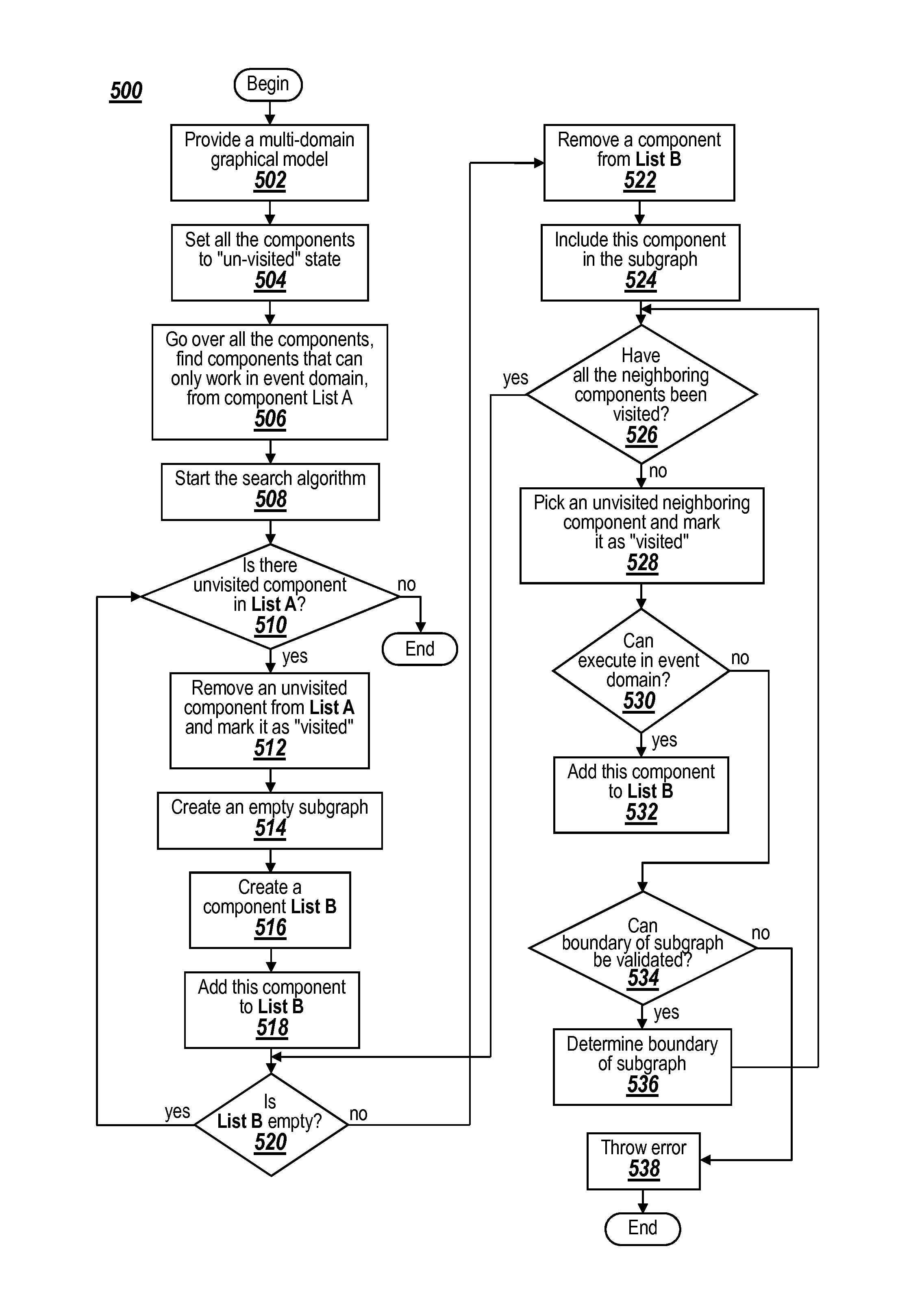
[0021]Exemplary embodiments may enable a multi-domain graphical model to be partitioned into multiple subgraphs. For example, a model may include multiple time-driven components and multiple discrete event-driven components. In this example, the discrete event-driven components may be partitioned into subgraphs. The partitioning of the subgraphs is determined based upon block connectivity and not model hierarchy. Each subgraph has a separate event calendar for scheduling and executing events in the subgraph. The execution of the subgraphs may be interleaved with execution of the time-driven components allowing data dependency between components to be modeled. The use of separate event calendars avoids shortcomings associated with using a single event calendar for all discrete event-driven components in a graphical model. In addition, the use of multiple event calendars allows types of models to be build and executed that cannot be executed using conventional single event calendar te...


PUM


Abstract

A Discrete Event System model created or provided in a time domain modeling and simulation environment and/or an event domain modeling and simulation environment may be divided into multiple independent regions, e.g. “subgraphs”, to achieve interleaved execution of the components from different domains. The subgraphs are automatically identified by the modeling and simulation environment during the compilation. Each subgraph consists of one or more interconnected event-driven components. Each subgraph is associated with an event calendar that controls the execution of the associated subgraph. Such multiple event calendar design enables multi-domain simulation, where event-driven components modeled by an event domain modeling environment and time-driven components modeled by a time domain modeling environment are simulated in an integrated fashion.

Description

RELATED APPLICATIONS[0001]The present application is a continuation in part of U.S. application Ser. No. 11 / 024,148, entitled “Method and System for Transferring Data Between a Discrete Event Environment and an External Environment,” filed Dec. 21, 2004, which claims priority to U.S. Provisional Patent Application Ser. No. 60 / 611,571, entitled “Method and System for Transferring Data Between a Discrete Event Environment and an External Environment”, filed Sep. 20, 2004, the contents of which are herein incorporated by reference.BACKGROUND INFORMATION[0002]A hybrid graphical model of a dynamic system may include one or more of graphical blocks from at least two different domains. For example, a hybrid Discrete Event System model may include time-driven components that may be modeled using a time domain modeling and simulation environment, e.g. Simulink®, and event-driven components that may be modeled using an event domain modeling and simulation environment, e.g. SimEvents®. Existin...

Claims


Application Information

Patent Timeline
IPC IPC(8): G06F17/50G06G7/48G06F7/60
CPCH04L41/22H04L41/06G06Q10/04H04L41/0883G06F17/5022H04L41/0879H04L41/0886G06F17/5009H04L41/20H04L41/145G05B2219/40322G06F30/33G06F30/20G06F30/3308
Inventor LI, WEICIOLFI, JOHN EDWARDCLUNE, MICHAEL I.
Owner THE MATHWORKS INC
Why Eureka
Try Eureka