

Dual slotted holder body for removal tool access
a tool and slotted technology, applied in the direction of screwdrivers, wrenches, cutting machines, etc., can solve the problems of shortening the useful life of the bit holder/bit block assembly, degrading the outside of the bit block,
- Summary
- Abstract
- Description
- Claims
- Application Information
AI Technical Summary
Benefits of technology
Problems solved by technology
Method used
Image

Examples
first embodiment
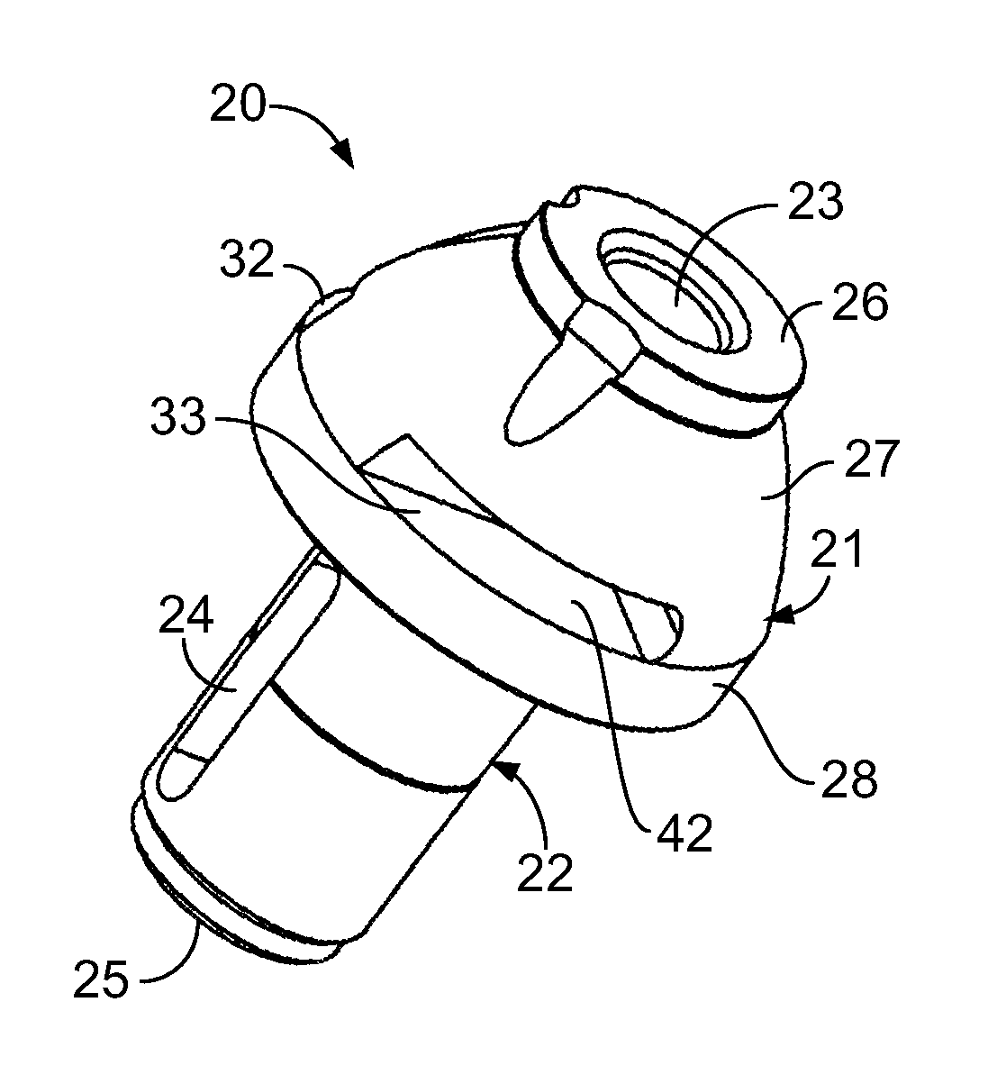
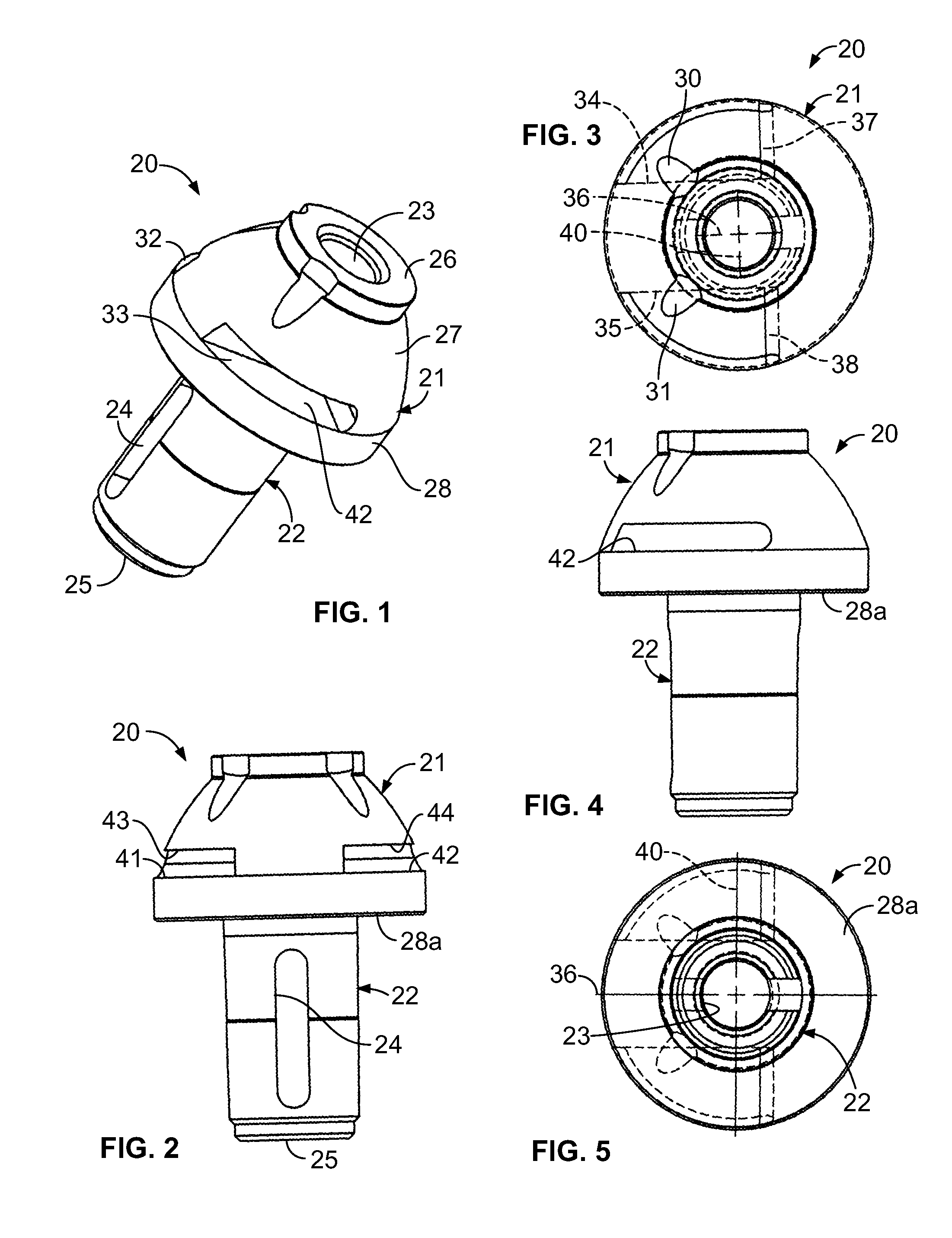
[0023]Referring to FIGS. 1-5, the first embodiment of the bit holder of the present invention, generally indicated at 20 is preferably made of forged steel, 4140, 8640, 4340 or the like. The bit holder includes an upper body, in this case a generally frustoconical body portion generally indicated at 21, and a lower generally cylindrical shank portion, generally indicated at 22. In this first preferred embodiment, the bit holder 20 includes a central aperture 23 through both the upper body portion 21 and the shank 22 in which a bit is preferably rotatably removably mounted during use. In use, the bit holder shank is ultra press fit into the bore of a bit holder block (101 in FIG. 10).
[0024]It will be appreciated that in some orientations, particularly when utilizing very hard materials, such as a diamond coating on the outer portion of the tip of the bit, the bit may be brazed into the aperture 23 to provide a combination bit / bit holder. In this and the other two embodiments describe...
second embodiment
The Second Embodiment
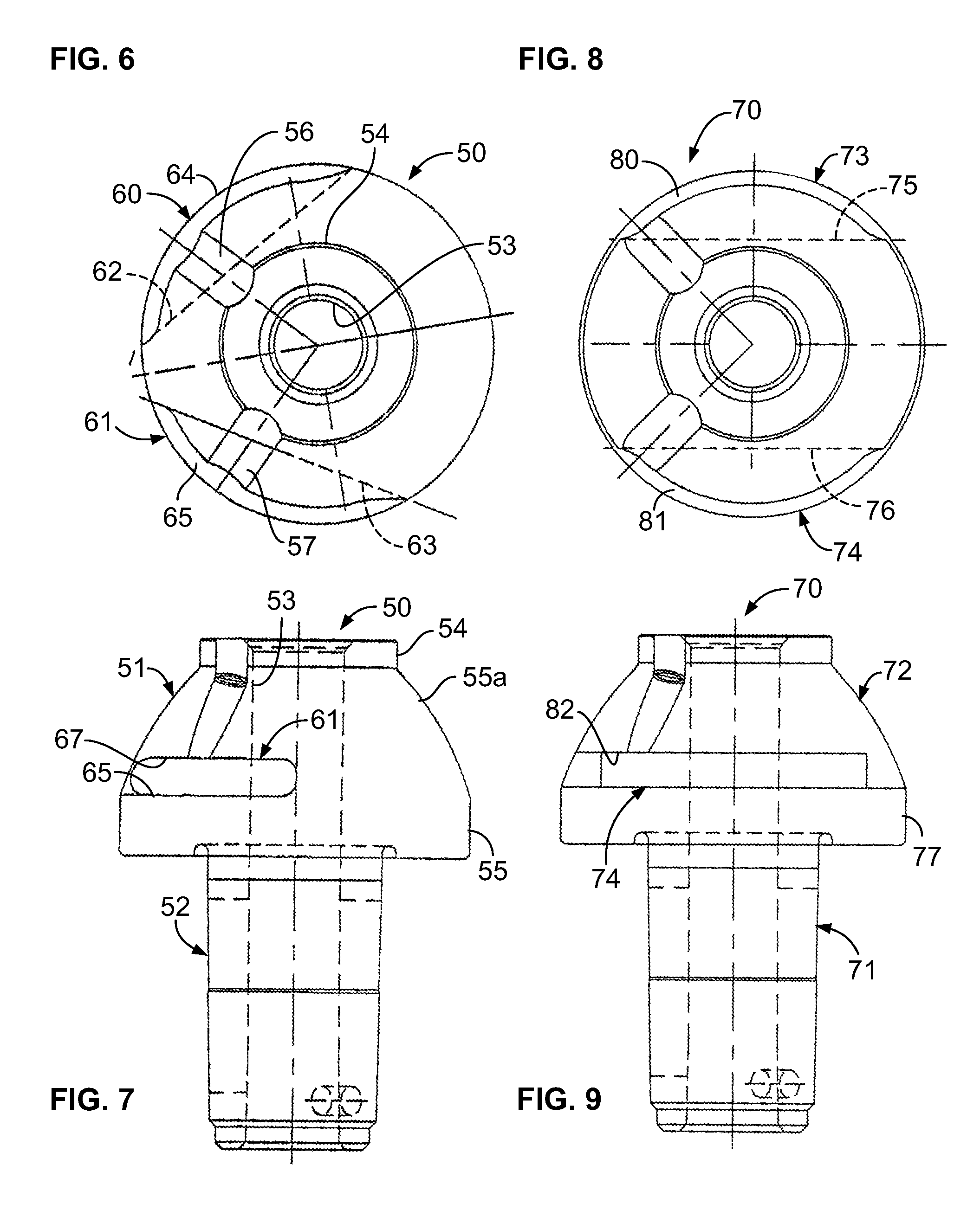
[0034]Referring now to FIGS. 6 and 7, a second preferred embodiment of the present invention, generally indicated at 50, like the first embodiment 20, includes a generally frustoconical upper body portion 51 and a lower, generally cylindrical shank portion 52. In this second embodiment, the shank portion 52 is identical to the shank portion 22 of the first embodiment, although it may have other configurations as shown in my prior patents noted above. Also, similarly to the first embodiment, a central axial bore 53 extends through both the upper body portion and the lower shank portion through the bit holder. Also, in this embodiment, the upper bit mounting portion 54 and the tire portion 55 are substantially identical to those respective portions of the first embodiment.
[0035]The notches 56 and 57 are similarly oriented to notches 30 and 31 of the first embodiment. However, the bottom portion of the notches differs in that they intersect the top of the opposed V...
third embodiment
The Third Embodiment
[0037]Referring to FIGS. 8 and 9, a third preferred embodiment of the present invention, generally indicated at 70, is similar in most respects to the first embodiment 20 with an identical shank 71 and a similar upper body portion 72, with the exception that a pair of opposed horizontal slots are somewhat shallower than the slots 32-33 shown in FIG. 1 but each extend substantially through a frustoconical middle of the upper body portion 20 such that there is no back wall as indicated at 37 and 38 of the first embodiment. Opposed parallel slots 73-74 shown partly in dotted line in FIG. 8 and slot only 74 shown in FIG. 9, in this preferred third embodiment, are somewhat shallower toward the longitudinal axis of the bit holder than slots 32, 33 of the first embodiment 20, being 1.875 inches apart from each other in the road milling size, but they extend through the upper body portion to the opposing side thereof, and are about ⅝ inch deep at their deepest part and 5...
PUM
| Property | Measurement | Unit |
|---|---|---|
| diameter | aaaaa | aaaaa |
| diameters | aaaaa | aaaaa |
| diameters | aaaaa | aaaaa |
Abstract
Description
Claims
Application Information