Optical path change type optical coupling element

a technology of optical coupling elements and optical paths, which is applied in the direction of optical elements, mountings, instruments, etc., can solve the problems of not being able to use and it is difficult to assembly the optical path converting type optical coupling elements b>1/b>

Inactive Publication Date: 2008-05-06
ORMON CORP
View PDF3 Cites 29 Cited by
  • Summary
  • Abstract
  • Description
  • Claims
  • Application Information

AI Technical Summary

Benefits of technology

[0009]An object of the present invention is to provide an optical path converting type optical coupling element able to be bidirectionally used and restrain the number of parts at its minimum.
[0011]In accordance with the optical path converting type optical coupling element of the present invention, after light incident by passing through a lens formed on one face is reflected on the total reflecting face, this light can be emitted from a lens formed on the other face to the exterior. It is possible to optically couple an optical fiber, a light emitting element, a light receiving element, etc. arranged so as to be opposed to the two faces of the resin molding body. Further, in this optical path converting type optical coupling element, the respective lenses are integrally arranged on the two faces of the resin molding body. Accordingly, no assembly of the resin molding body and the lenses is required, and the optical axis adjustment of the lenses, etc. are not required so that the optical path converting type optical coupling element can be simply manufactured and its cost can be reduced. Further, since the lenses are respectively arranged on the two faces, there is an advantage able to bidirectionally couple the optical fiber, the light emitting element, the light receiving element, etc.
[0013]In the embodiment mode of the present invention, the lens for converting light incident so as to be approximately emitted from one point into parallel light is used. Accordingly, the light emitted from the optical fiber, etc. becomes the parallel light and is guided into the resin molding body, and is incident to the total reflecting face. As this result, leakage of the light on the total reflecting face is reduced, and coupling efficiency of the light can be improved.
[0019]In still another embodiment mode of the present invention, the hollow is formed in a portion of the resin molding body on the side opposed to the total reflecting face. Accordingly, a shrinkage cavity on the total reflecting face, a warp of the resin molding body, etc. at the molding time can be restrained at its minimum. In particular, if the inner face of the hollow is formed in parallel with the total reflecting face, and the distance from each lens to the total reflecting face along the optical axis of each lens formed on the two faces, and the distance from the inner face of the hollow to the total reflecting face are approximately equal to each other, it is also possible to reduce the shrinkage cavity of the lens together with the shrinkage cavity of the total reflecting face.

Problems solved by technology

Therefore, no bidirectional coupling can be performed between the optical fiber and the light receiving element or a light emitting element.
Further, no optical path converting type optical coupling element 1 can be used when the bidirectional coupling is performed between the optical fibers.
Therefore, it becomes difficult to assembly the optical path converting type optical coupling element 1.
Further, since the optical fiber must be arranged in a position far from an original set position, it also becomes difficult to make the optical axis adjustment of the optical fibers.
Further, since the number of parts is increased, it takes time and labor to assemble the optical path converting type optical coupling element, and its cost is raised.

Method used


Image

  • Optical path change type optical coupling element
  • Optical path change type optical coupling element
  • Optical path change type optical coupling element

Examples


Embodiment Construction

[0050]The embodiments of the present invention will next be concretely explained. However, the present invention is not limited to the following embodiments, but can be naturally modified in the scope not departing from the technical idea of the present invention.

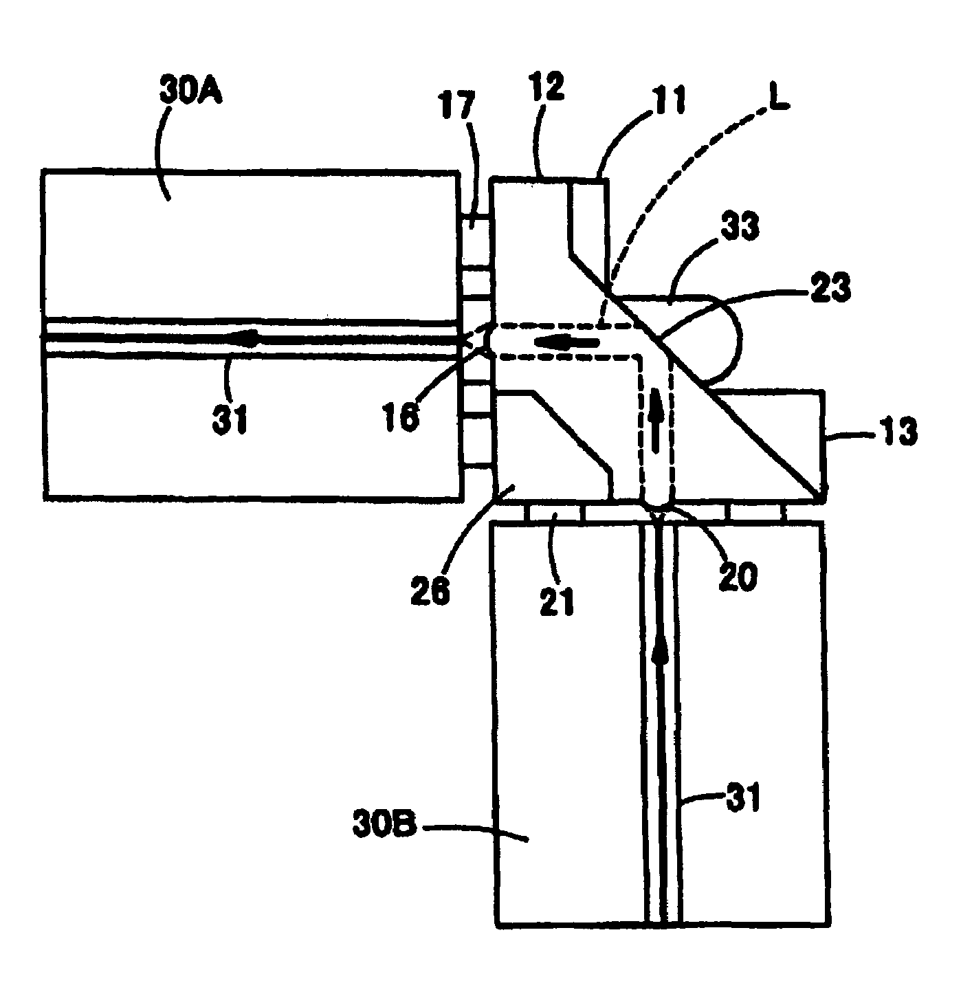
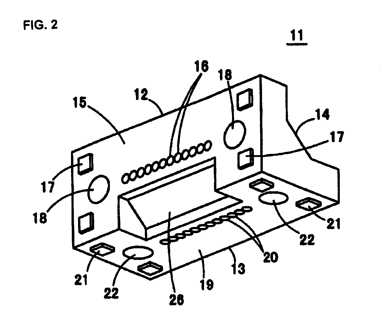
[0051]FIG. 2 is a perspective view showing an optical path converting type optical coupling element 11 in accordance with one embodiment of the present invention and seen upward on the front face side. FIG. 3 is a perspective view seen downward on the rear face side of the optical path converting type optical coupling element 11. FIGS. 4, 5 and 6 are respectively a front view, a bottom view and a plan view of the optical path converting type optical coupling element 11. FIG. 7 is an X-X line sectional view of FIG. 4. FIG. 8 is a Y-Y line sectional view of FIG. 4. This optical path converting type optical coupling element 11 is entirely integrally molded by transparent resin. For example, the optical path converting type opt...


PUM


Abstract

A resin molding body has two faces (front face 15 and lower face 19) perpendicular to each other, and also has a total reflecting face 23 approximately having an angle of 45° with respect to these two faces. Plural collimating lenses 16 and a spacer 17 are integrally formed on one face. Plural collimating lenses 20 and a spacer 21 are also integrally formed on the other face. A wall taking-away portion 26 is concavely arranged between the two faces so as to be located on the rear face side of the total reflecting face 23. Guide holes 18, 22 for inserting guide pins thereinto and connected to optical connectors, etc. are bored on the two faces of the resin molding body.

Description

TECHNICAL FIELD[0001]The present invention relates to an optical path converting type optical coupling element used in optical coupling between light transmitting paths.BACKGROUND ART[0002]FIG. 1 is a schematic sectional view showing the structure of a conventional optical path converting type optical coupling element 1 (e.g., JP-A-9-281302). In this optical path converting type optical coupling element 1, plural micro lenses 3 are arranged on the front face (or lower face) of a glass substrate 2. An inclining face 4 is formed in the upper portion of the rear face of the glass substrate 2, and the lower face 5 of the glass substrate 2 is formed so as to become a horizontal face.[0003]FIG. 1 also shows a using state of this optical path converting type optical coupling element 1. Each of plural optical fibers 6 is opposed to each micro lens 3 arranged on the front face of the optical path converting type optical coupling element 1. A light receiving element 8 mounted onto a substrate...

Claims


Application Information

Patent Timeline
Patent Type & Authority Patents(United States)
IPC IPC(8): G02B17/00G02B6/32G02B6/26G02B6/38G02B6/42
CPCG02B6/3829G02B6/4214G02B6/264G02B6/3885G02B6/4201G02B6/4204G02B6/4249G02B6/4262G02B6/426G02B6/424G02B6/4244G02B6/4255H01L2224/48137G02B7/182
Inventor YAMAMOTO, RYOTSUCHIDA, MAKOTOTANI, MASAYOSHINAGASAKA, SHOGOTANAKA, HIROKAZU
Owner ORMON CORP
Why Eureka
Try Eureka