
Deer feeder filling apparatus

a filling apparatus and feeder technology, applied in the field of deer feeders, can solve the problems of inconvenient refilled and regular refilled of such apparatuses, and the method is even more time-consuming, and achieve the effect of reducing time and effor

Inactive Publication Date: 2014-01-07
GORE MICHAEL K +1
View PDF19 Cites 12 Cited by
  • Summary
  • Abstract
  • Description
  • Claims
  • Application Information

AI Technical Summary

Benefits of technology

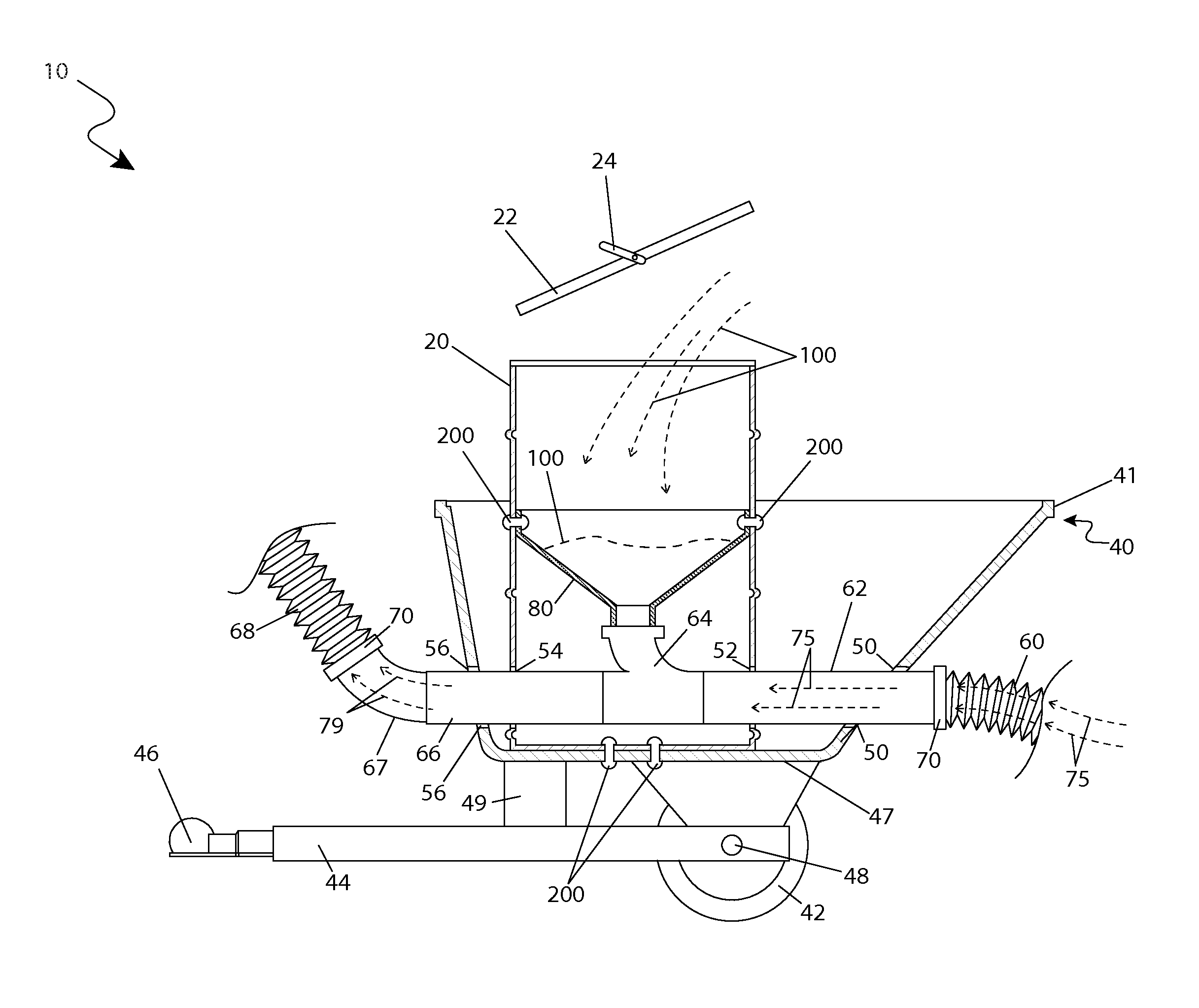
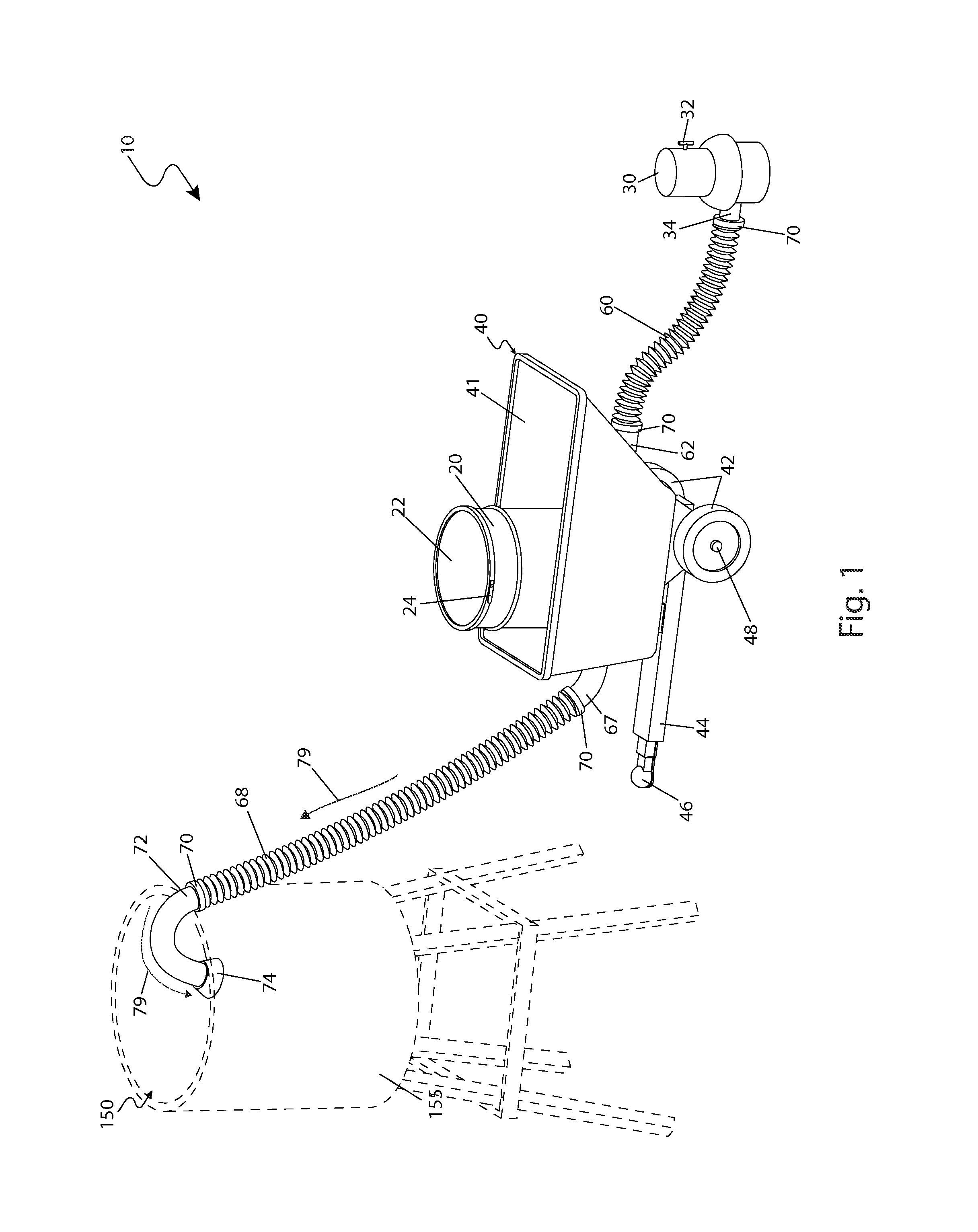
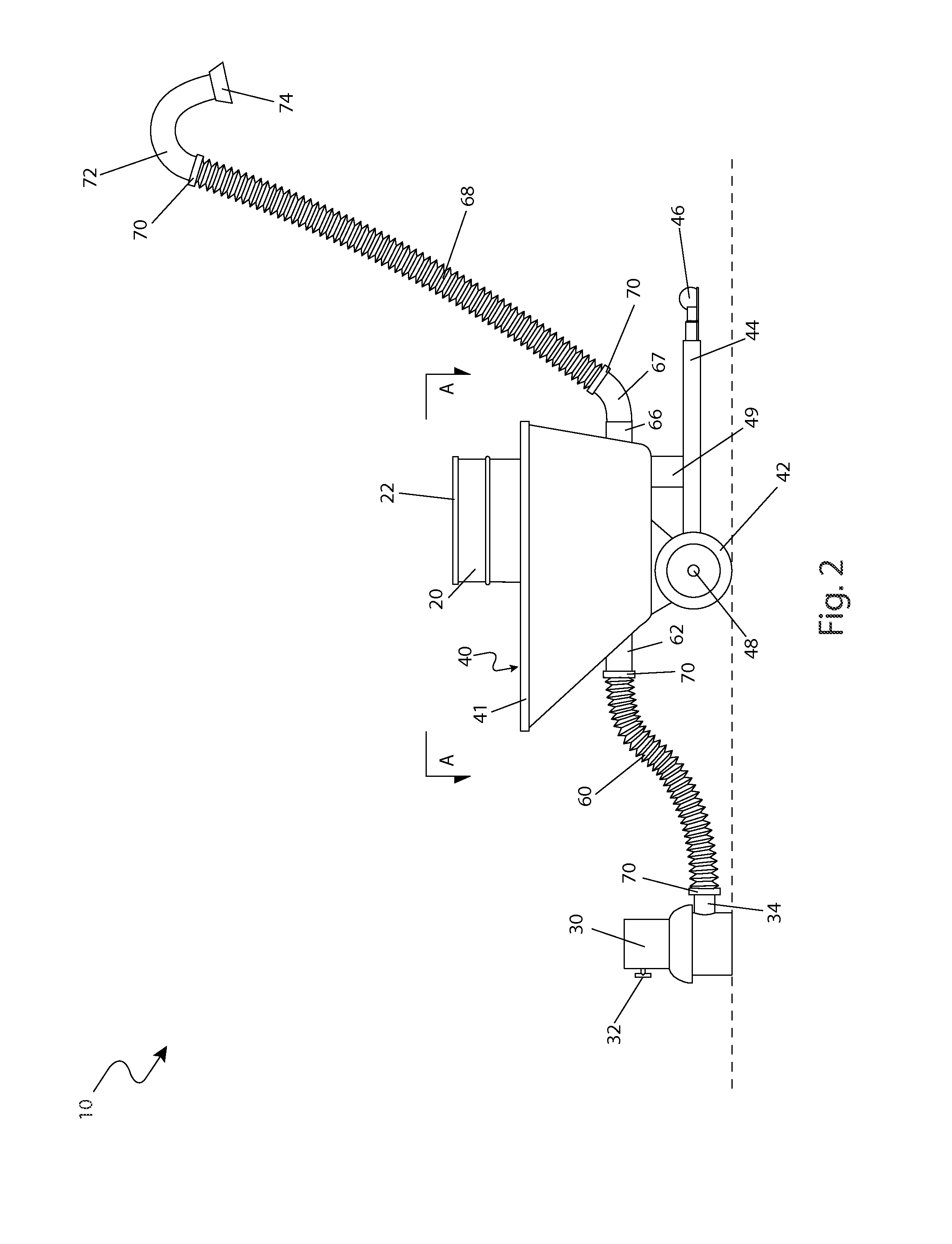
The present invention is a device that helps make the task of refueling a deer feeder easier and safer. It includes a mobile cart, a blower, and a container for holding deer feed. The apparatus can be easily attached to a vehicle, using a hitch receiver. A flexible hose connects the container to the feeder, allowing the deer feed to be easily pumped into the feeder. A lid prevents the feed from being wasted while the blower is in use. The method of use involves positioning the blower near the feeder, connecting the hose to the container, and adding the deer feed into the container. The feed can then be pumped into the feeder using the blower. Overall, this invention reduces the time and effort required to refuel deer feeders.

Problems solved by technology

While most of these feeders work, a primary inconvenience of all such apparatuses is that they need to be refilled on a regular basis.
However, this is not both time consuming and somewhat dangerous due to the elevated nature of the feeder.
This is method is even more time consuming and requires significant physical exertion.
Many such apparatuses require significant time and physical exertion to refill.
Also, many such apparatuses require additional complex portions to install and maintain.
Furthermore, many such apparatuses are aesthetically unpleasing.
In addition, many such apparatuses may inhibit the efficacy of an associated feeder.

Method used


Image

  • Deer feeder filling apparatus
  • Deer feeder filling apparatus
  • Deer feeder filling apparatus

Examples


Embodiment Construction

[0056]The best mode for carrying out the invention is presented in terms of its preferred embodiment, herein depicted within FIGS. 1 through 3. However, the invention is not limited to the described embodiment and a person skilled in the art will appreciate that many other embodiments of the invention are possible without deviating from the basic concept of the invention, and that any such work around will also fall under scope of this invention. It is envisioned that other styles and configurations of the present invention can be easily incorporated into the teachings of the present invention, and only one particular configuration shall be shown and described for purposes of clarity and disclosure and not by way of limitation of scope.

[0057]The terms “a” and “an” herein do not denote a limitation of quantity, but rather denote the presence of at least one of the referenced items.

[0058]The present invention describes a deer feeder filling apparatus (herein described as the “apparatu...


PUM


Abstract

An automated filling apparatus which propels various deer feed into an elevated deer feeder comprises a cart having a mounted container which is towed by a vehicle to a feeder location. A base of the cart receives an air duct connected to an air blower which supplies an air flow. The apparatus introduces a flow of deer feed into the air flow which is in turn conveyed upwardly into the elevated deer feeder via a second opposing air duct being connected to an elongated flexible hose having an elbow portion at its upper end and retained upon an upper lip of the deer feeder. After activating the blower, a quantity of deer feed is poured into the container and is propelled upward through the tubing and dispensed into the container portion of the deer feeder.

Description

RELATED APPLICATIONS[0001]The present invention was first described in and claims the benefit of U.S. Provisional Application No. 61 / 309,075 filed Mar. 1, 2010, the entire disclosures of which are incorporated herein by reference.FIELD OF THE INVENTION[0002]The present invention relates generally to deer feeders, and in particular, to an apparatus including an air pump for filling a deer feeder with feed.BACKGROUND OF THE INVENTION[0003]Many people enjoy the presence of deer and other wild game in their yards and on their property. In order to attract such animals, many place elevated feeding stations filled with corn, grains or other feed which entice the animals to stay, feed and hopefully return on a daily basis.[0004]While most of these feeders work, a primary inconvenience of all such apparatuses is that they need to be refilled on a regular basis. This refilling operation is most often done by climbing a ladder and pouring feed into a top portion of the feeder. However, this i...

Claims


Application Information

Patent Timeline
Patent Type & Authority Patents(United States)
IPC IPC(8): B60P1/60
CPCB60P1/60A01K5/0208
Inventor GORE, MICHAEL K.GORE, KATHLEEN A.
Owner GORE MICHAEL K
Learn More