Supercharge Your Innovation With Domain-Expert AI Agents!

Scanning EUV interference imaging for extremely high resolution patterning

a patterning and interference imaging technology, applied in the field of interferometric lithography, can solve the problems of limiting the resolution of these systems, poor numerical aperture, and difficulty in using conventional masks, reticles and patterning arrays to achieve, and achieve the effect of high resolution patterning

Inactive Publication Date: 2014-01-07
ASML HLDG NV
View PDF17 Cites 8 Cited by
  • Summary
  • Abstract
  • Description
  • Claims
  • Application Information

AI Technical Summary

Benefits of technology

The patent is about a new system and method for EUV lithography that solves the problem of limited numerical aperture and allows for high resolution patterning. In simpler terms, this technology improves the ability to make very precise patterns using light.

Problems solved by technology

When resolutions reach nanometer scale, such as 30-100 nm, it is very difficult to use conventional masks, reticles, and patterning arrays to accomplish this.
However, many of these systems suffer from poor numerical apertures, for example on the order of 0.25, that limit the resolution of these systems, for example, on the order of 26 nm line / space (L / S).

Method used


Image

  • Scanning EUV interference imaging for extremely high resolution patterning
  • Scanning EUV interference imaging for extremely high resolution patterning
  • Scanning EUV interference imaging for extremely high resolution patterning

Examples


Embodiment Construction

[0024]This specification discloses one or more embodiments that incorporate the features of this invention. The disclosed embodiment(s) merely exemplify the invention. The scope of the invention is not limited to the disclosed embodiment(s). The invention is defined by the claims appended hereto.

[0025]The embodiment(s) described, and references in the specification to “one embodiment”, “an embodiment”, “an example embodiment”, etc., indicate that the embodiment(s) described can include a particular feature, structure, or characteristic, but every embodiment cannot necessarily include the particular feature, structure, or characteristic. Moreover, such phrases are not necessarily referring to the same embodiment. Further, when a particular feature, structure, or characteristic is described in connection with an embodiment, it is understood that it is within the knowledge of one skilled in the art to effect such feature, structure, or characteristic in connection with other embodiment...


PUM


Abstract

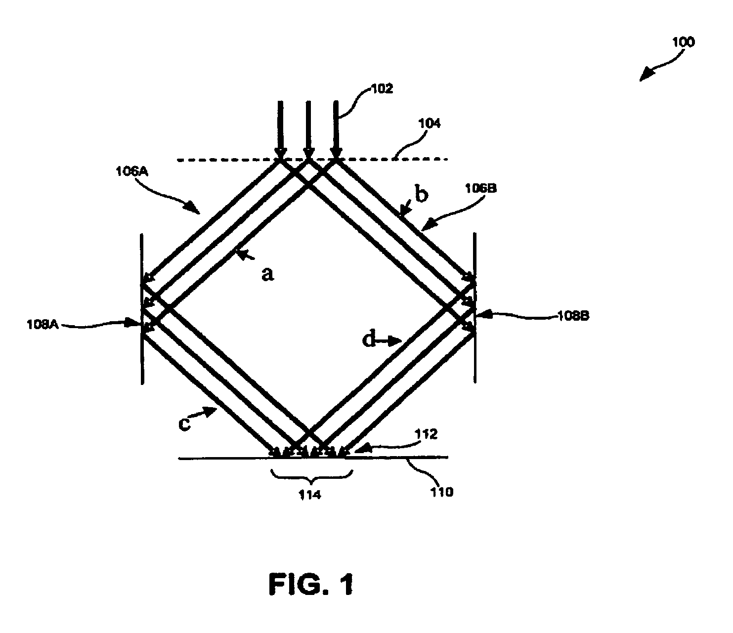
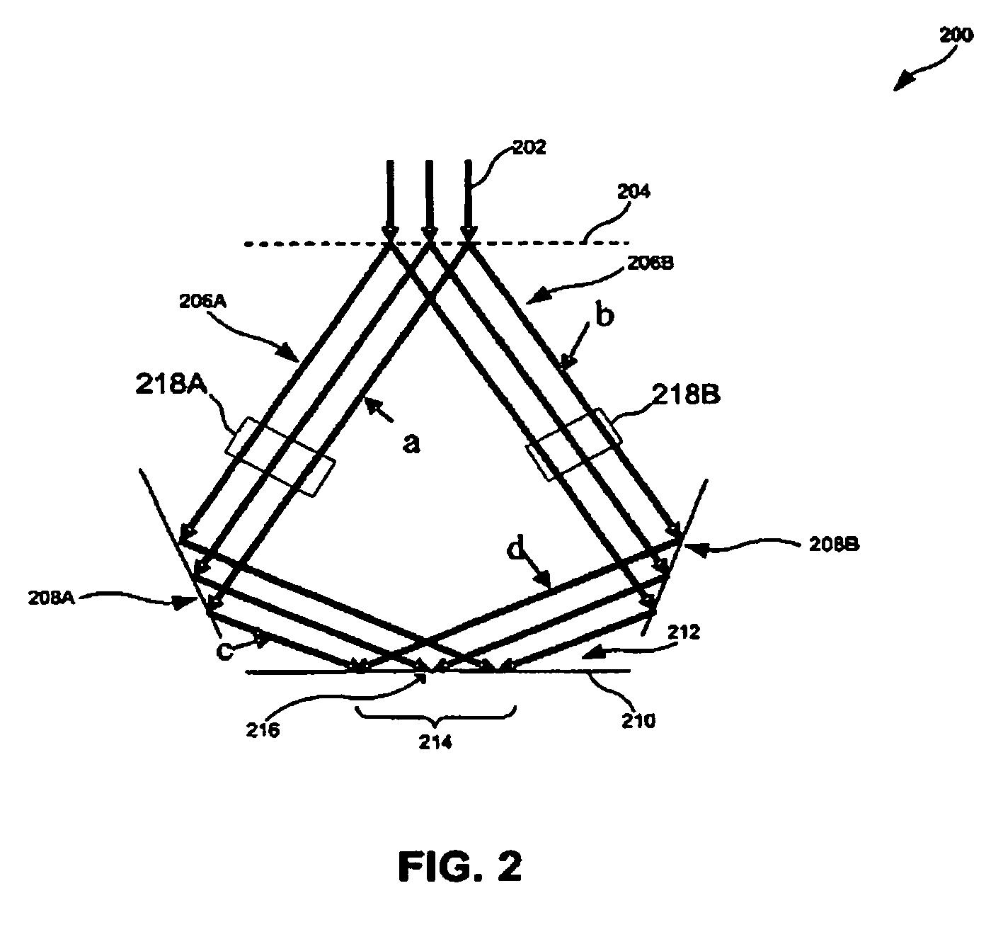
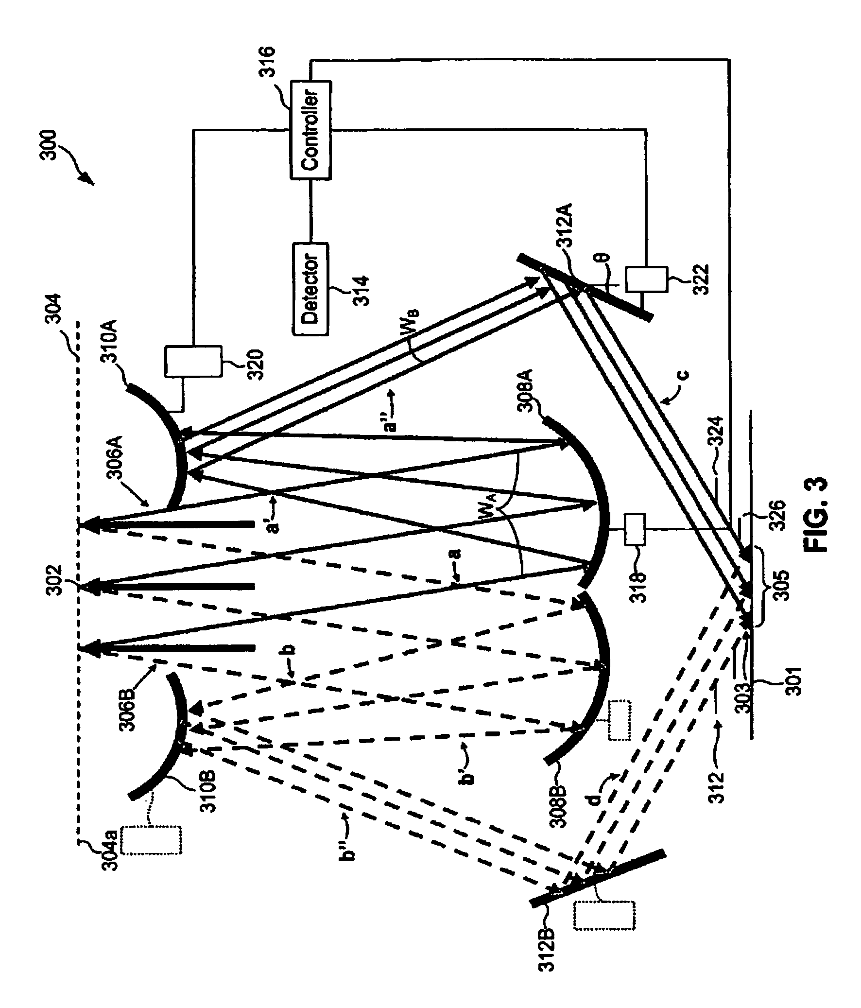
A system and method are provided for writing patterns onto substrates. First and second beams of extreme ultraviolet (EUV) radiation are produced. An exposure unit is used to project the first and second beams of EUV radiation onto a substrate. The first and second beams of radiation interfere with each other to expose a first set of parallel lines at an exposure field of the substrate.

Description

CROSS-REFERENCE TO RELATED APPLICATIONS[0001]This application claims the benefit of U.S. provisional application 61 / 006,185, which was filed on 28 Dec. 2007, and which is incorporated herein in its entirety by reference.BACKGROUND[0002]1. Field of the Invention[0003]The present invention relates to lithographic systems, and more particularly to interferometric lithography.[0004]2. Related Art[0005]A lithographic apparatus is a machine that applies a desired pattern onto a substrate or part of a substrate. A lithographic apparatus can be used, for example, in the manufacture of flat panel displays, integrated circuits (ICs) and other devices involving fine structures. In a conventional apparatus, a patterning device, which is commonly referred to as a mask or a reticle, can be used to generate a circuit pattern corresponding to an individual layer of a flat panel display (or other device). This pattern can be transferred onto all or part of the substrate (e.g., a glass plate), by ima...

Claims


Application Information

Patent Timeline
Patent Type & Authority Patents(United States)
IPC IPC(8): G03B27/70
CPCG03F7/70266G03F7/70408G03F7/2006H01L21/0274
Inventor SEWELL, HARRY
Owner ASML HLDG NV
Features
  • R&D
  • Intellectual Property
  • Life Sciences
  • Materials
  • Tech Scout
  • Unparalleled Data Quality
  • Higher Quality Content
  • 60% Fewer Hallucinations
Learn More