Micro-projector

a technology of projection display and projector, which is applied in the field of compact mobile projection display system, can solve the problems of inability to properly display graphical html pages or high-resolution images/videos on display screens, and the small size of display screens used in handheld devices, etc., and achieves the effect of not being commercially available and displaying green laser diodes

Inactive Publication Date: 2011-02-17
EXPLAY
View PDF12 Cites 146 Cited by
  • Summary
  • Abstract
  • Description
  • Claims
  • Application Information

AI Technical Summary

Benefits of technology

[0007]A mobile hand held version of projection displays imposes considerable limitations on the system design, configuration and technologies. Common requirements for the mobile projection display include battery operation, passive heat removal, small weight and size (inducing a requirement for compact optical dimensions) and relatively low cost, combined with still high brightness and quality of the projected image. These requirements result inter alia in a very special choice of light sources and optics. Choice of light sources, having high spatial coherence, requires a special care for the granularity and speckle reduction.
[0011]The matching between the aspect ratio of the lenslet and that of the active surface of the SLM optimizes the efficiency of the illumination system. It should be noted that the optimized efficiency of the illumination system provides a sufficiently bright image at limited power consumption and small footprint (25×25 mm max) and volume (3 to 5 cc) of the optical unit.
[0013]The small size of the projection display of the present invention is achieved by significantly reducing the optical path of light within the device as well as reducing the cross-section of a light beam involved in the illumination and projection path. The illumination system of the projection is configured to direct most of the power generated by a light source unit towards a spatial light modulator (SLM) with the following properties: high spatial uniformity, limited numerical aperture and preferably telecentric structure of the rays within the dimensions of the SLM active surface, substantial reduction of the near field and far-field speckle effects.
[0015]In another embodiment, three laser sources, providing light of three primary colors, are used. The use of laser sources provides monochromatic light which is well defined in directions of propagation and enables manufacturing of a very compact device. However, the laser source requires special beam shaping and speckle reduction techniques. The creation of a primary speckle pattern can be observed on the surface of a screen, when a coherent beam of light passes through an optical system. The primary speckle pattern is caused by the random interference between different light beams of the projected coherent light thus reducing the image quality. The projection display of the present invention is configured for eliminating or at least significantly reducing the speckle effect by the use of a de-speckling unit and superimposing on the SLM a set of several beams each of them illuminating all the active surface of the SLM. In particular, the illumination system is configured for reducing a speckle effect in the laser light. The illumination system may comprise at least one de-speckling unit accommodated in the optical path of the at least one laser beam upstream of the DMLA arrangement. The de-speckling unit performs a speckle reduction based on a concept of time averaging of the speckle patterns, while light scattering element (diffuser) produces a light scattered pattern randomly varying in both space and time, thereby reducing the speckle effect. This diffuser, also called a “pupil diffuser” is located within the illumination system of the projection display, in the optical path of at least one laser beam upstream of the beam shaping DMLA arrangement.
[0022]The de-speckling unit and the preferably telecentric beam shaping unit might be shared by all or part of the primary color channels. Alternatively, the primary color channels may have their own such units. In order to shorten the optical path of light within the device, a telephoto design of the lenses may be used in laser illumination channels. Therefore, the illumination system may comprise a telephoto negative lens, such that the optical path of light within the projection display is reduced while the effective focal length of the projection display is maintained.
[0026]Moreover, the projection display has compact features in which the light propagation path through the projection display substantially does not exceed a few tens of millimeters.

Problems solved by technology

However, the small-size display screen, used in handheld devices, remains a bottleneck for such applications.
For example, a graphical HTML page or a high-resolution image / video cannot be properly displayed on these display screens due to their small size.
With regards to green laser sources, the green laser diodes are not yet commercially available, but the diode pumped solid state (DPSS) lasers with frequency doubling have already reached a peak power exceeding 50 mW.
Projector systems based on high power lamps, LEDs or other incoherent sources may feature high etendue (i.e. product of the squared beam divergence over source area) that causes low collection efficiency of the projector optical system due to limited F-number of the illumination system and projection lens.
As a result, a greater amount of power consumption is required at the illumination source for the sufficient amount of brightness of the projected image.
Therefore projector systems based only on high power lamps, or other incoherent sources are quite bulky, difficult to handle, limited in their mobility and therefore might not be down-scalable to very compact portable handheld projection devices.

Method used


Image

  • Micro-projector
  • Micro-projector
  • Micro-projector

Examples


Embodiment Construction

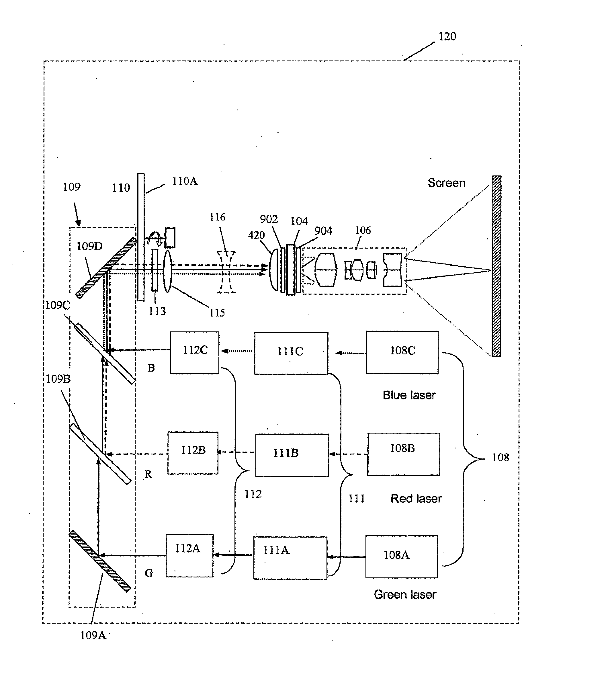
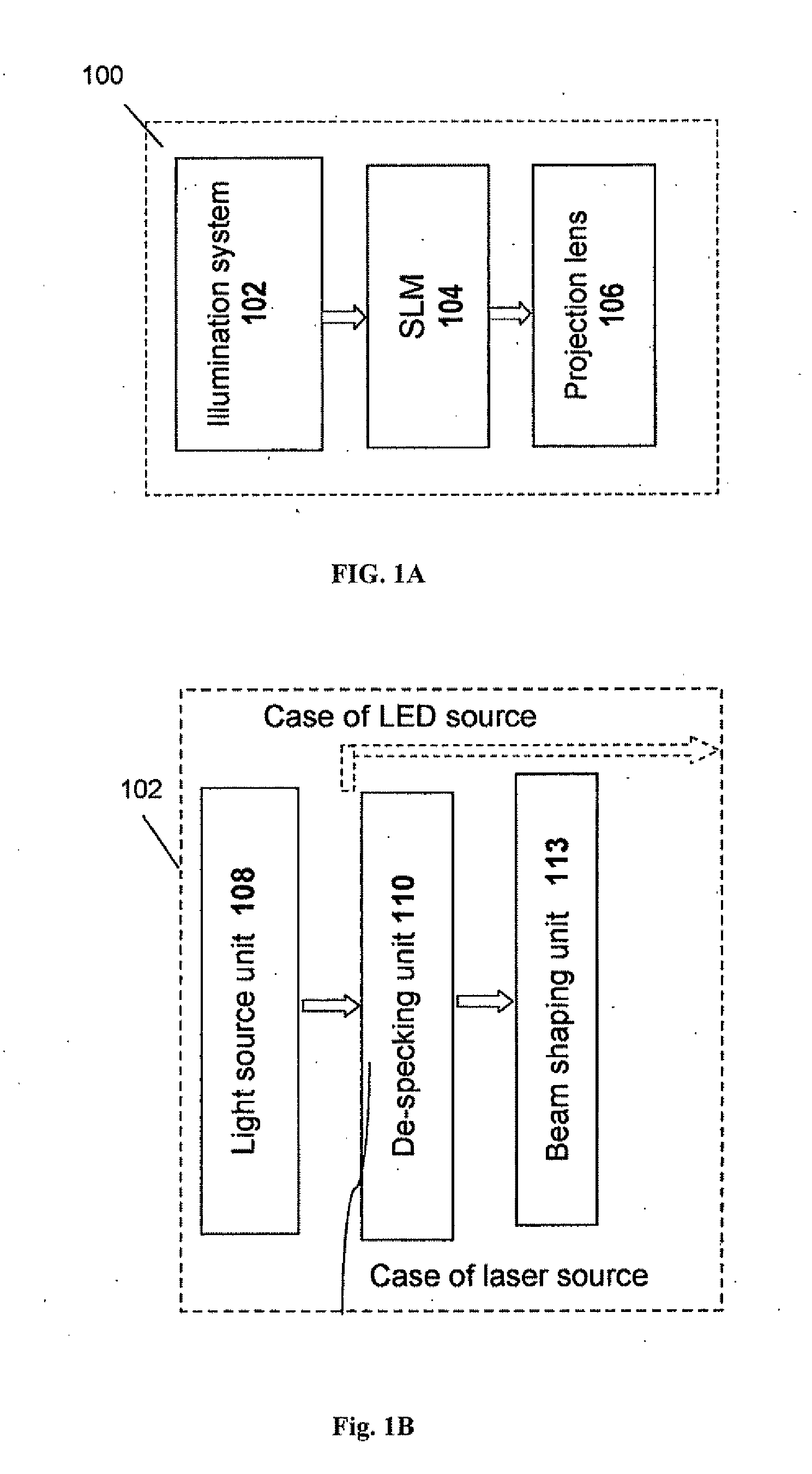
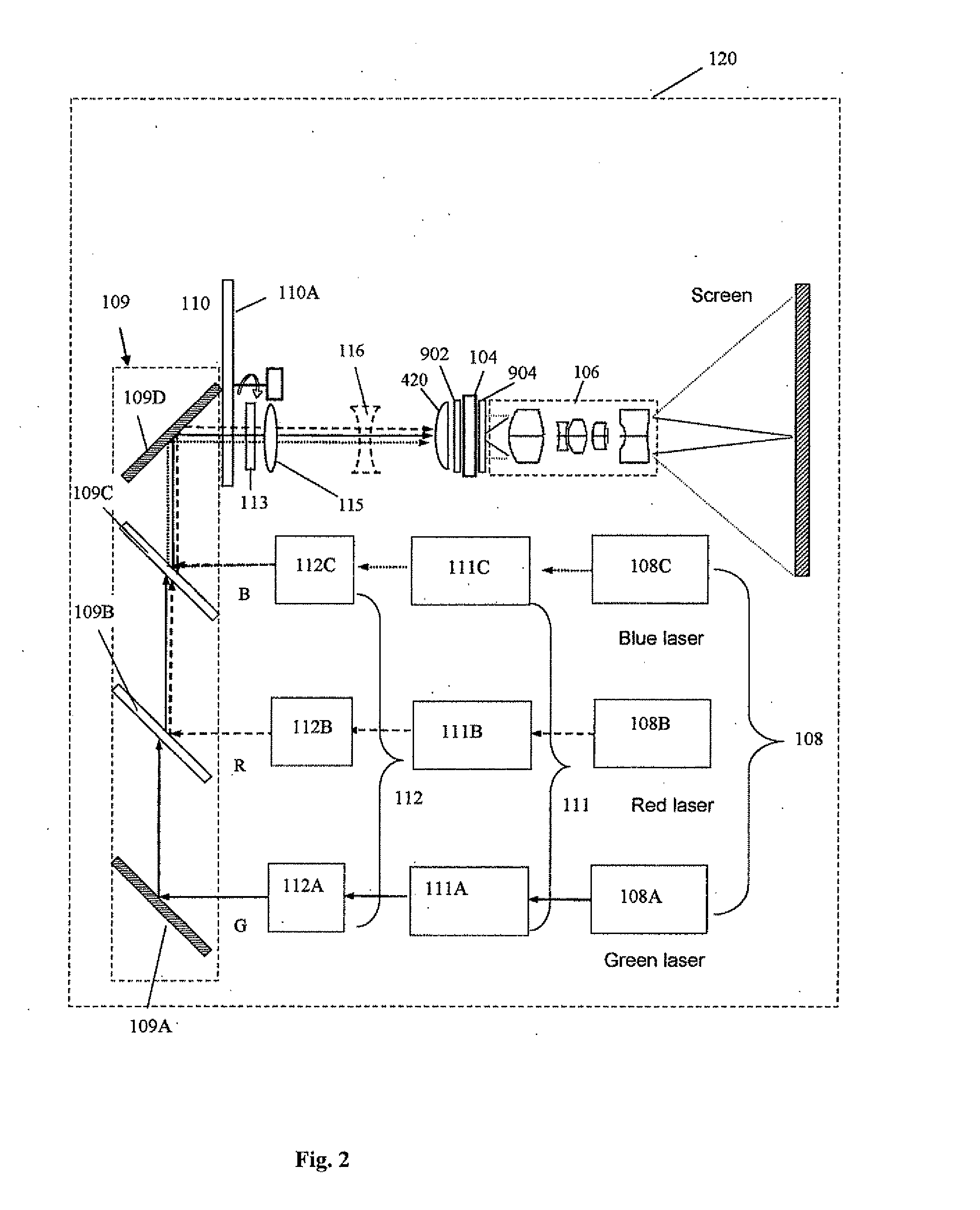
[0067]Reference is made to FIG. 1A illustrating a schematic representation of an example of a compact projection display 100 of the present invention. The projection display includes an illumination system 102 for producing one or more light beams, e.g. multiple light beams of different wavelengths, typically primary colors (RGB) or YRGB or a wider set of colors; a spatial light modulator (SLM) system 104, which may be configured as LCD, T-LCOS, LCOS or DMD panel; and a projection optics, typically a lens unit 106. It should be noted that the projection display may include a separate SLM for each light illumination channel, or a common SLM for at least two channels.

[0068]To facilitate understanding, the same reference numbers will be used for identifying some of the components that are common in all the examples.

[0069]Reference is made to FIG. 1B illustrating a block diagram of the illumination system 102 comprising a light source unit 108 which in the present example has a number o...


PUM


Abstract

The present invention provides a projection display comprising an illumination system comprising at least one laser source unit and configured and operable for producing one or more light beams; a spatial light modulating (SLM) system accommodated at output of the illumination system and comprising one or more SLM units for modulating light incident thereon in accordance with image data; and a light projection optics for imaging modulated light onto a projection surface. The illumination system comprises at least one beam shaping unit comprising a Dual Micro-lens Array (DMLA) arrangement formed by front and rear micro-lens arrays (MLA) located in front and rear parallel planes spaced-apart along an optical path of light propagating towards the SLM unit, the DMLA arrangement being configured such that each lenslet of the DMLA directs light incident thereon onto the entire active surface of the SLM unit, each lenslet having a geometrical aspect ratio corresponding to an aspect ratio of said active surface of the SLM unit.

Description

FIELD OF THE INVENTION[0001]The present invention relates to projection display systems and particularly to a compact mobile projection display systems, compatible with the portable electronic devices.BACKGROUND OF THE INVENTION[0002]Projection display systems have conventionally been used for displaying enlarged images in meetings, for entertainment purposes, personal and automotive applications, and the like. In recent years, projection display systems have advanced into the field of handheld and mobile devices with image / video and Internet-surfing applications, such as mobile phones, PDAs, portable media players, compact memory devices, companion devices, communication networks equipment, laptop and pocket personal computers, GPS navigators. However, the small-size display screen, used in handheld devices, remains a bottleneck for such applications. For example, a graphical HTML page or a high-resolution image / video cannot be properly displayed on these display screens due to the...

Claims


Application Information

Patent Timeline
Patent Type & Authority Applications(United States)
IPC IPC(8): G02B27/48G03B21/14
CPCG02B3/005G02B5/04H04N9/3197H04N9/3161H04N9/3173H04N5/74
Inventor NIZANI, ZVIALONI, MEIRYALOV, SHIMONRACHUM, UZIRAND, JACOB
Owner EXPLAY
Why Eureka
Try Eureka