
Tail thruster control for projectiles

a projectile and thruster technology, applied in direction controllers, instruments, weapons, etc., can solve the problems of reducing reducing the accuracy of the projectile, and reducing the restoring force of the projectile, so as to maximize the lift of the projectile, accurate guide the projectile, and minimize the effect of restoring forces

Active Publication Date: 2014-01-07
BAE SYST INFORMATION & ELECTRONICS SYST INTERGRATION INC
View PDF15 Cites 5 Cited by
  • Summary
  • Abstract
  • Description
  • Claims
  • Application Information

AI Technical Summary

Benefits of technology

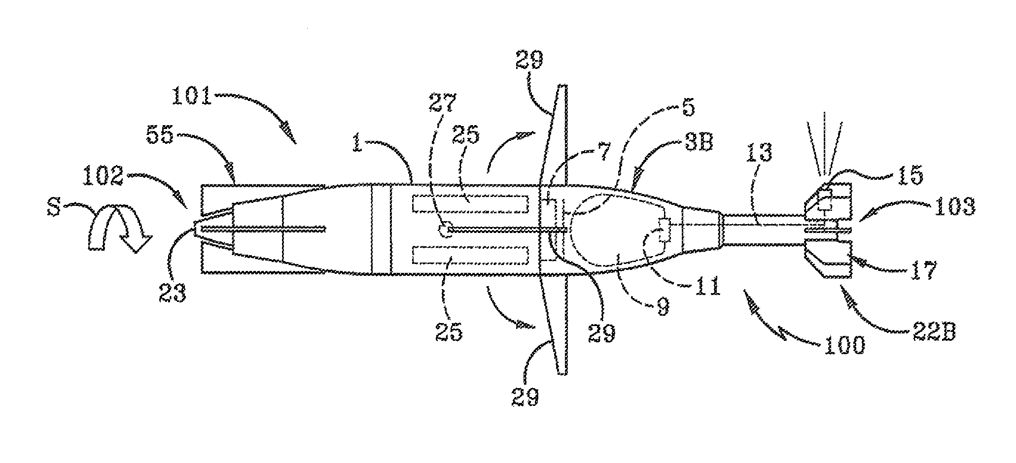
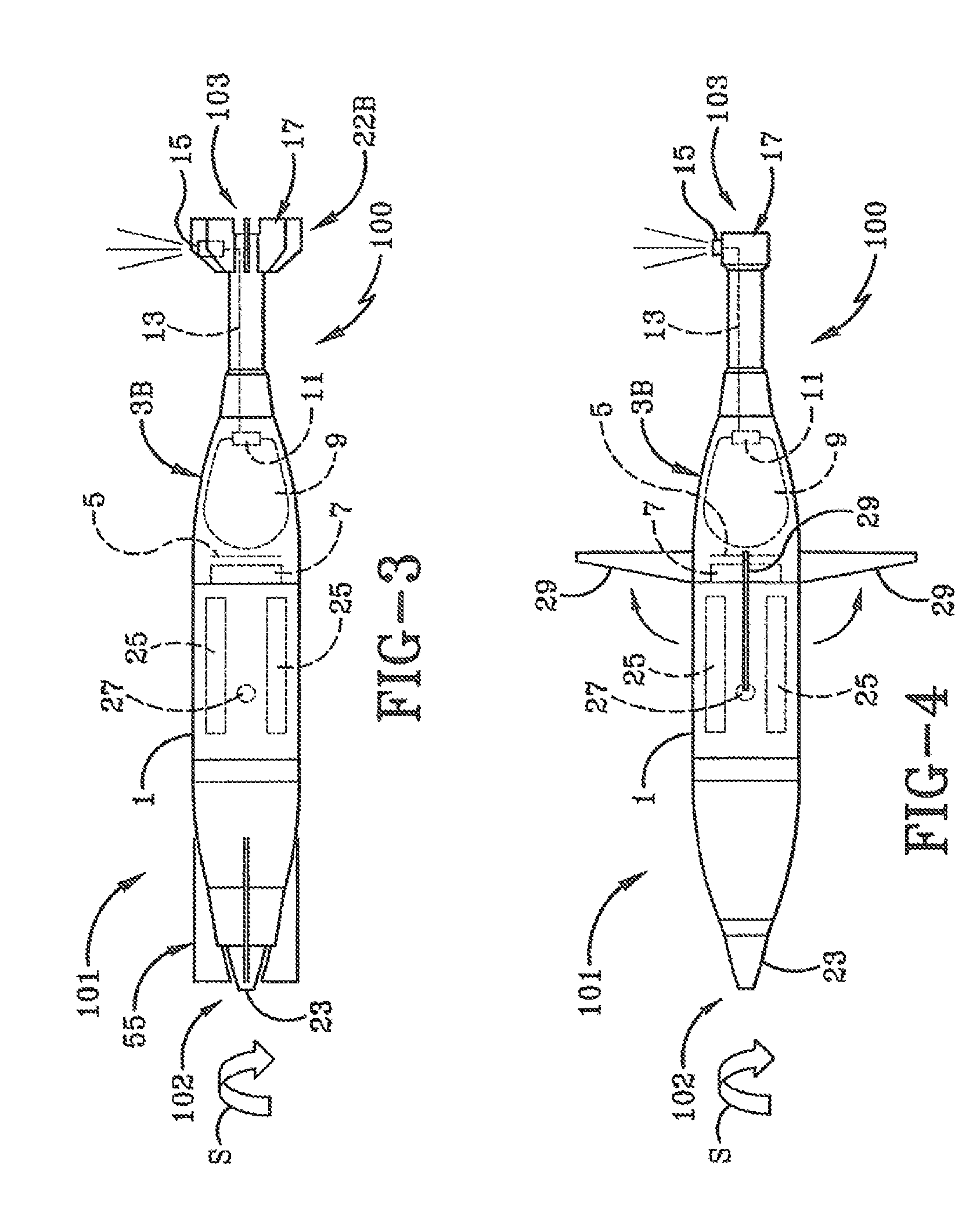
The invention is a guidance system for projectiles that allows them to be accurately guided to their target using a tail-kit approach. The system includes a screw interface for the tail boom assembly and a nozzle that ejects pulses of gas perpendicular to the direction of flight to control the angle of attack and lift of the projectile. The system can be configured with flip-out surfaces and strakes to further enhance the lift and maneuver acceleration capability of the projectile. The method involves storing gas in a chamber attached to the projectile and releasing bursts of gas to control the angle of attack and lift of the projectile. The system and method provide improved accuracy and efficiency in guiding projectiles to their target.

Problems solved by technology

Generally, guidance systems added to the nose cannot truly be kits as they decouple the fuse from the safe and arm system.
In this case, a rapid continuous and scattered impact of rounds causes the enemy to take cover.
A guided round can actually slow the pace in this type of mission due to its programming requirements where an unguided round with inherent dispersion can be rapidly fired by dropping rounds in fast succession into the tube.
Due to the desire of scattered impacts, a guided round in this case is wasted.
Because the tail has to push on the round in the opposite direction of the desired maneuver in order to hold angle of attack, the lifting surfaces actually subtract lift reducing total maneuver capability.
Addition of flip out surfaces to enhance the tail area is complicated by the need to provide a motor or a mechanism driven by a shaft within the current tail volume.
The volume required for motors and the mechanism further reduces the available lift generated by the tail.
Analysis of the current tail area, disregarding the motor or mechanism, shows insufficient lift to steer the round.
Given the extreme environments and constrained volumes, any kind of mechanically controlled rear lifting element is difficult if not impossible for an explosively launched round.

Method used


Image

  • Tail thruster control for projectiles
  • Tail thruster control for projectiles
  • Tail thruster control for projectiles

Examples


Embodiment Construction

[0028]The novel concept of the preferred embodiment of the invention includes a gas bottle, valve and thruster nozzle to control angle of attack of a projectile. A spin in the direction of arrow S is induced in the round and a valve fires a thruster phased with the round's spin to control the round's attitude in inertial space. This system is implemented in a field mountable tail kit assembly allowing selection of a guided versus unguided round.

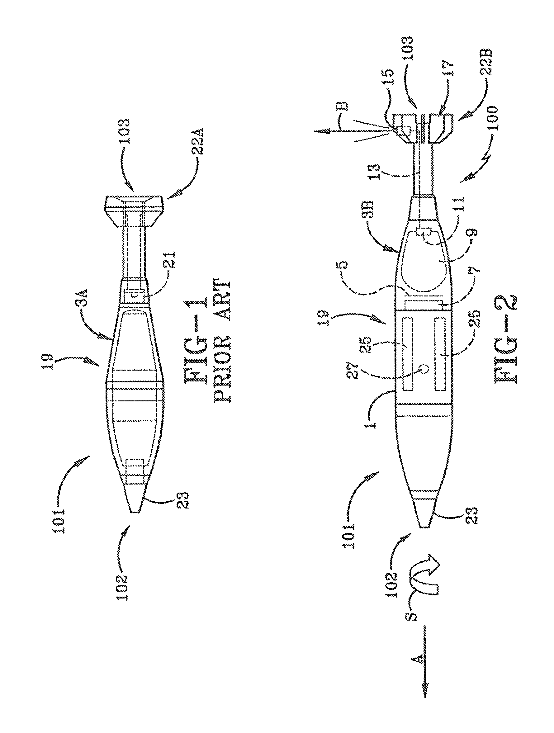
[0029]FIG. 1 illustrates a conventional round 101 (e.g., projectile, munition) that has not been modified by a thruster controller. In this figure, the base round 19 has a standard, fuse 23 and a screw off tail and boom assembly 22A with female threads attached to the munition body male threads 21. The munition 101 has a front end 102 and a back end 103.

[0030]The round 101 can be converted to include the preferred embodiment of the thruster controller 100 that attaches to the male threads of the munition body 21 as shown in FIG. 2. A shroud 1...


PUM


Abstract

A system and method for guiding a projectile is presented. A nozzle system includes a boom assembly body that can be attached to a rear end of a projectile. A gas tank in the boom assembly contains pressurized gas. Fins are attached to the boom assembly body to guide the projectile. A valve lets a pulse of gas out of the gas tank. A nozzle expels the pulse of gas to control an angle of attack and lift of the projectile to guide the projectile to a target.

Description

BACKGROUND OF THE INVENTION[0001]1. Field of Invention[0002]The current invention relates generally to apparatus, systems and methods for guiding projectiles. More particularly, the apparatus, systems and methods relate to a tail kit for guiding projectiles. Specifically, the apparatus, systems and methods provide for a tail kit with a thruster that controls the body angle of attack and the lift of a projectile when guiding the projectile.[0003]2. Description of Related Art[0004]Generally, precision mortar systems are implemented with a guidance kit that is added to the nose of the round. Lift is generated by controlling the body angle of attack. Lifting elements in front of the center of gravity (CG) are used to control the body angle of attack and also generate additive lift. These lifting elements can be thrusters, aerodynamic surfaces such as canards or wings, air diverters that collect air at the nose and push it out the side or thrusters. Generally, guidance systems added to t...

Claims


Application Information

Patent Timeline
Patent Type & Authority Patents(United States)
IPC IPC(8): F42B10/60F42B10/00F42B10/66
CPCF42B10/66F42B10/666F42B10/06F41G7/2246F42B10/663
Inventor FREY, JR., ROBERT, D.
Owner BAE SYST INFORMATION & ELECTRONICS SYST INTERGRATION INC
Learn More