Automatic inspection apparatus for detecting stains on polarizing plate using color difference analysis and inspection method thereof

a technology of color difference analysis and automatic inspection, which is applied in the direction of optically investigating flaws/contamination, optical radiation measurement, instruments, etc., can solve the problems of difficult to produce products having uniform product quality, uneven brightness of the screen, and striped stains on the polarizing plate. to achieve the effect of accurate inspection results of actual stains

Active Publication Date: 2014-01-07
SHANJIN OPTOELECTRONICS (NANJING) CO LTD
View PDF11 Cites 5 Cited by
  • Summary
  • Abstract
  • Description
  • Claims
  • Application Information

AI Technical Summary

Benefits of technology

[0011]An aspect of the present invention provides an automatic inspection apparatus and method for detecting stains on a polarizing plate using color difference analysis allowing for accurate inspection results of actual stains by image data analysis, without processing an image of a target polarizing plate into analyzable image data.

Problems solved by technology

However, striped stains may be present on the polarizing plate manufactured as described above in a machine direction (MD) thereof due to uneven dyeing, poor attachment, or the like.
When stains are severely formed thereon, the brightness of a screen is not uniform, and thus, final product defects may result therefrom.
However, this inspection method has problems in that it may be difficult to produce products having uniform product quality since the degree of defects in final products is subjectively determined by the inspectors.
An excessive exposure time may cause a difference between stains obtained from RGB data extracted from the image data and stains observed with the naked eye by inspectors.
Further, according to the related art, stains are quantified by utilizing intensity data from among the extracted image data, and accordingly, it is difficult to verify stains caused by a delicate color difference.

Method used


Image

  • Automatic inspection apparatus for detecting stains on polarizing plate using color difference analysis and inspection method thereof
  • Automatic inspection apparatus for detecting stains on polarizing plate using color difference analysis and inspection method thereof
  • Automatic inspection apparatus for detecting stains on polarizing plate using color difference analysis and inspection method thereof

Examples


example 1

[0100]A non-elongated PVA film was dyed in a dye bath at a temperature of 25° C. to 30° C. for a retention time of 1 to 5 minutes, and elongated 5 to 6 times to thereby prepare a polarizing element. Here, ‘UZ grade’ having a haze and a thickness of 800n were used as a protective film of the polarizing element.

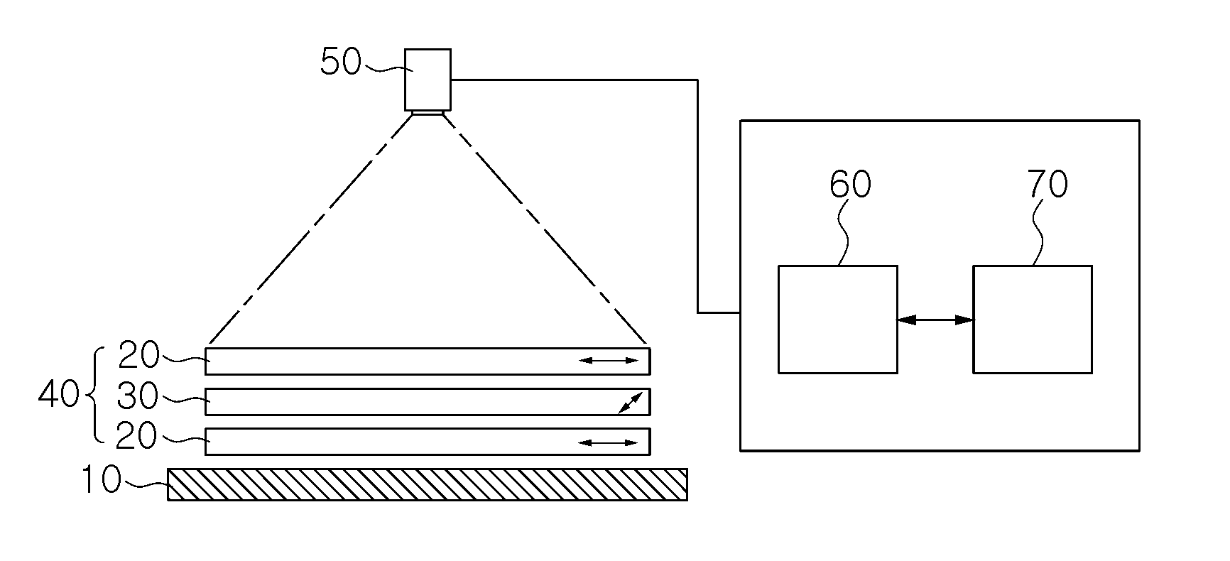
[0101]After the manufactured polarizing plate was mounted on a reference polarizing plate (manufactured by LG Chemicals, RB60SR10, a level of transmittance: 39.7%), it was irradiated with light using a 42-inch backlight (LG display, a color temperature of 10,000K). Here, an absorption axis of the manufactured polarizing plate was inclined with respect to that of the reference polarizing plate in order to allow a level of brightness of the manufactured polarizing plate to be 5 nits, while being irradiated with light. Thereafter, an image of the polarizing plate was captured above the backlight using a digital camera (Nikon, D3100 Zoom lens), and the captured image was transferre...

example 2

[0102]A polarizing plate was prepared in the same manner as in Example 1, except that ‘WVEA’ (manufactured by Fujifilm Corporation, having a thickness of 60 μm) and ‘UZ Clear TAC’ (manufactured by Fujifilm Corporation, having a thickness of 60 μm) were used as a protective film. The manufactured polarizing plate was subjected to the same process as in Example 1 to calculate a maximum amplitude value and quantify the degree of staining. As a result of inspection of the polarizing plate, the maximum amplitude value and the numerical data value indicating the degree of staining thereof were stated in Table 1.

example 3

[0103]A polarizing plate was prepared in the same manner as in Example 1, except that ‘UZ’ and ‘UZ Clear’ having a thickness of 60 μm were used as a protective film. The manufactured polarizing plate was subjected to the same process as in Example 1 to calculate a maximum amplitude value and quantify the degree of staining. As a result of inspection of the polarizing plate, the maximum amplitude value and the numerical data value indicating the degree of staining thereof were stated in Table 1.


PUM


Abstract

There is provided an automatic inspection apparatus and method for detecting stains on a polarizing plate using color difference analysis. The automatic inspection apparatus includes an inspection unit including at least one reference polarizing plate and a target polarizing plate or polarizing element mounted on the at least one reference polarizing plate; a light source unit disposed on one surface of the inspection unit and irradiating the inspection unit with light; an imaging unit disposed on the other surface of the inspection unit, imaging the target polarizing plate or polarizing element, and transferring an image thereof; and an arithmetic operation unit performing color difference analysis for individual inspection regions of the image of the target polarizing plate or polarizing element transferred by the imaging unit and detecting a blurred stain.

Description

CROSS-REFERENCE TO RELATED APPLICATIONS[0001]This application claims the priorities of Korean Patent Application Nos. 10-2011-0040370 filed on Apr. 28, 2011 and 10-2011-0040371 filed on Apr. 28, 2011, in the Korean Intellectual Property Office, the disclosures of which are incorporated herein by reference.BACKGROUND OF THE INVENTION[0002]1. Field of the Invention[0003]The present invention relates to an automatic inspection apparatus and method for detecting stains on a polarizing plate, and more particularly, to an automatic inspection apparatus and method for detecting stains on a polarizing plate, designed to objectively determine the degree of staining on a polarizing plate using color difference analysis, monitor defects in a polarizing plate in a production line in real time, and automatically inspect the quality of a polarizing plate after cutting thereof.[0004]2. Description of the Related Art[0005]A polarizing plate is an optical device used to allow light polarized in a ce...

Claims


Application Information

Patent Timeline
Patent Type & Authority Patents(United States)
IPC IPC(8): G01J4/00
CPCG01N21/94
Inventor LEE, CHONG-KUNRAH, KYUN-ILKIM, TAE-HUNLEE, YOO-MINLEE, SANG-DEOK
Owner SHANJIN OPTOELECTRONICS (NANJING) CO LTD
Why Eureka
Try Eureka