Method for processing an ultrasonic analog signal, digital signal processing unit and ultrasonic inspection device

an analog signal and ultrasonic technology, applied in the field of processing ultrasonic analog signals, digital signal processing units and ultrasonic inspection devices, can solve the problems of difficult detection of such flaws in test objects, limited application, and inability to reliably detect flaws, etc., to achieve a high degree of flexibility

Inactive Publication Date: 2014-08-21
GE SENSING & INSPECTION TECH GMBH
View PDF4 Cites 3 Cited by
  • Summary
  • Abstract
  • Description
  • Claims
  • Application Information

AI Technical Summary

Benefits of technology

[0022]Means for decomposing the digital ultrasonic data by the first level of a wavelet filter algorithm and means for altering the wavelet coefficients by a threshold analysis are provided behind the respective A / D converter of each signal path. In a first embodiment of the signal processing unit according to the present invention, it moreover comprises means for the inverse transformation of the combined ultrasonic signal by the second level of the wavelet filter algorithm with the altered wavelet coefficients. In the second embodiment of the signal processing unit according to the present invention, it moreover comprises, for each signal path, means for the separate inverse transformation of the decomposed ultrasonic signal by the second level of the wavelet filter algorithm with the, optionally individually, altered wavelet coefficients. Subsequently, means for generating the combined ultrasonic signal from the inversely transformed ultrasonic data of both signal paths / amplifier branches are provided. Thus, the second embodiment of the signal processing unit according to the present invention is characterized in that means for decomposing the digital ultrasonic data by the first level of a wavelet filter algorithm and means for, possibly individually, altering the wavelet coefficients by a threshold analysis are provided behind the respective A / D converter of each signal path, and that thereafter, means for the joint inverse transformation of the decomposed ultrasonic signal data by the second level of the wavelet filter algorithm with the altered wavelet coefficients are provided in each signal path, which is followed by means for recombining these ultrasonic data inversely transformed in each signal path into a combined digital ultrasonic signal, which has the advantage of a high dynamic range.
[0030]Moreover, this makes a high degree of flexibility with regard to the adjustment possible, so that an ultrasonic inspection device using the signal processing unit according to an embodiments of the present invention can be adapted to different applications when, for example, the threshold values for the threshold analysis are selected in a variable manner. Thus, it can be avoided that natural effects are possibly not taken into account after the calibration, as could otherwise be the case when standard filters are used.
[0031]Due to the conversion of the ultrasonic analog signal into at least two digital partial signals that are amplified differently and subjected to a threshold analysis, it is possible, in particular, to also capture defects close to the surface in an inspected object. The reflected signal curve of a defect close to the surface is very small in comparison to the boundary surface signal. The size of the boundary surface signal can be greater by an order of magnitude of one hundred than the size of the signal of the defect. Thus, the larger signal would overload the amplifier, and the signal of the defect contained in the larger signal curve would be lost or would not be detectable. By eliminating the boundary surface signal, however, weaker signals can also be displayed. This allows an examiner to obtain more precise inspection results for defects close to the surface.

Problems solved by technology

Even though the pulse echo methods have been established methods in the field of material testing for many years, their application was generally limited to such inspection cases in which flaws are to be detected in the full test object volume.
However, if flaws occur in the vicinity of such structures of the test object which themselves reflect the ultrasonic pulses used for the inspection, the detection of such flaws in the test object is difficult.
In such a case, the pulse reflected at the flaw overlaps with the pulse reflected at the reflecting structure of the test object, so that a reliable detection of the flaw is often problematic or even impossible.
However, possible geometry echoes can lead to a relatively weak signal of a flaw being incapable of being displayed if it is superimposed by other signals.
Large amplitude differences of several received signals thus render smaller signals difficult to detect.
However, these components and circuits may in turn involve new problems with regard to the calibration and with respect to the reliability and consistency of the results, which have to be resolved.

Method used


Image

  • Method for processing an ultrasonic analog signal, digital signal processing unit and ultrasonic inspection device
  • Method for processing an ultrasonic analog signal, digital signal processing unit and ultrasonic inspection device
  • Method for processing an ultrasonic analog signal, digital signal processing unit and ultrasonic inspection device

Examples


first embodiment

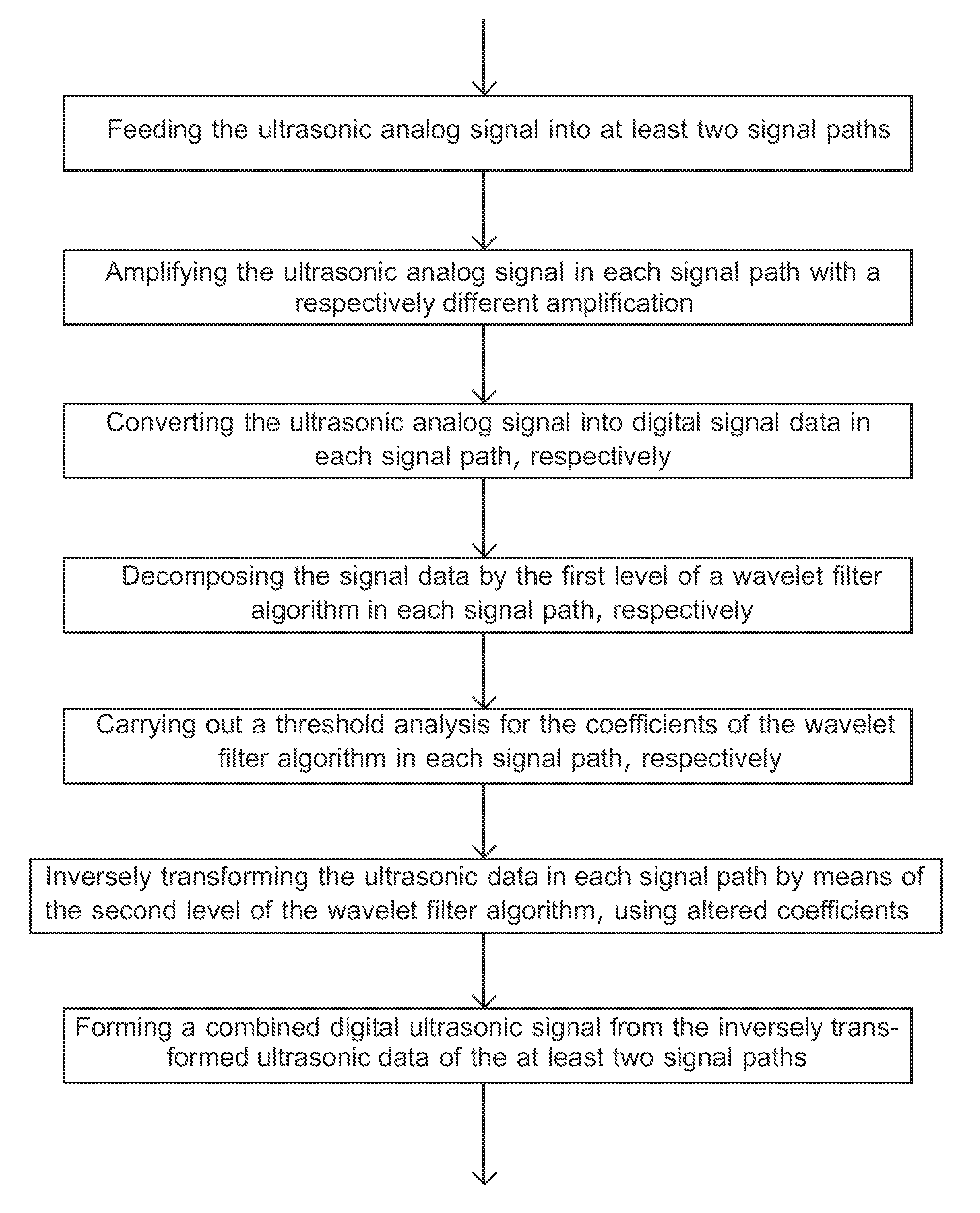
[0049]These main steps of the method according to the present invention for processing an ultrasonic analog signal and their order are also shown in the flow chart of FIG. 4.

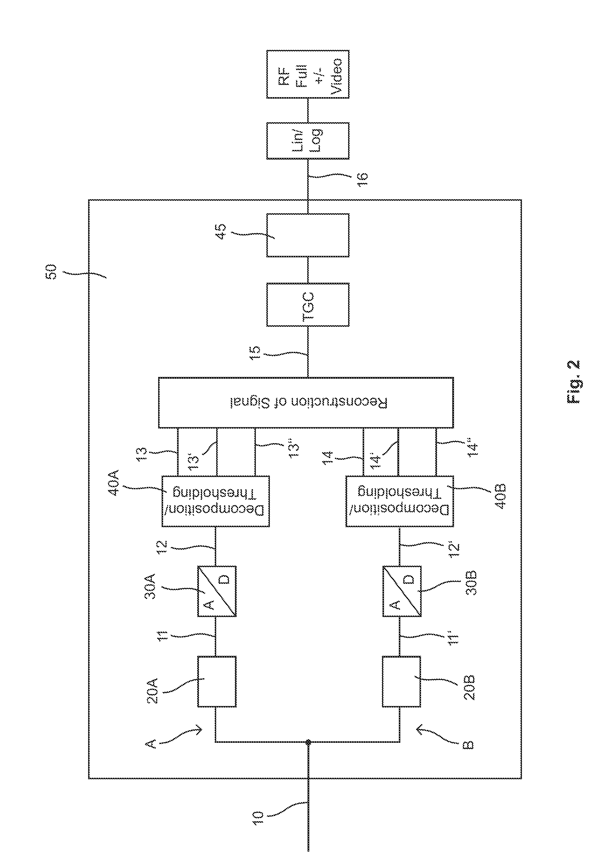
[0050]FIG. 5 shows a schematic representation of the mode of operation of the components of an inventive signal processing unit according to the second embodiment of the present invention. This corresponds completely to the first embodiment of the present invention shown in FIG. 2, with the exception of the differences described below. In the two signal paths A and B, three signal data 13, 13′, 13″ and 14, 14′, 14″, two of which, however, are immediately set to zero for the purpose of reducing the DC offset, are generated for each signal path by separate decomposition and threshold analysis from the digitized signals 12, 12′. Thus, two signal data 13′ and 13″, respectively, as well as 14′ and 14″, respectively, result in each case for the two signal paths, which are separately inversely transformed in each signa...

second embodiment

[0051]The main steps of the method according to an embodiment of the present invention for processing an ultrasonic analog signal and their order are also shown in the flow chart of FIG. 6.

[0052]The digital ultrasonic signal 15 obtained in this manner can then be subjected to further processing steps in both embodiments of the present invention. For example, a time gain compression (TGC) can take place and the signal can be supplied to another band-pass filter 45. Shrinkable coefficients and individually selectable wavelets can be used for the band-pass filter. Moreover, the wavelet coefficients are subjected to a threshold analysis also in this case.

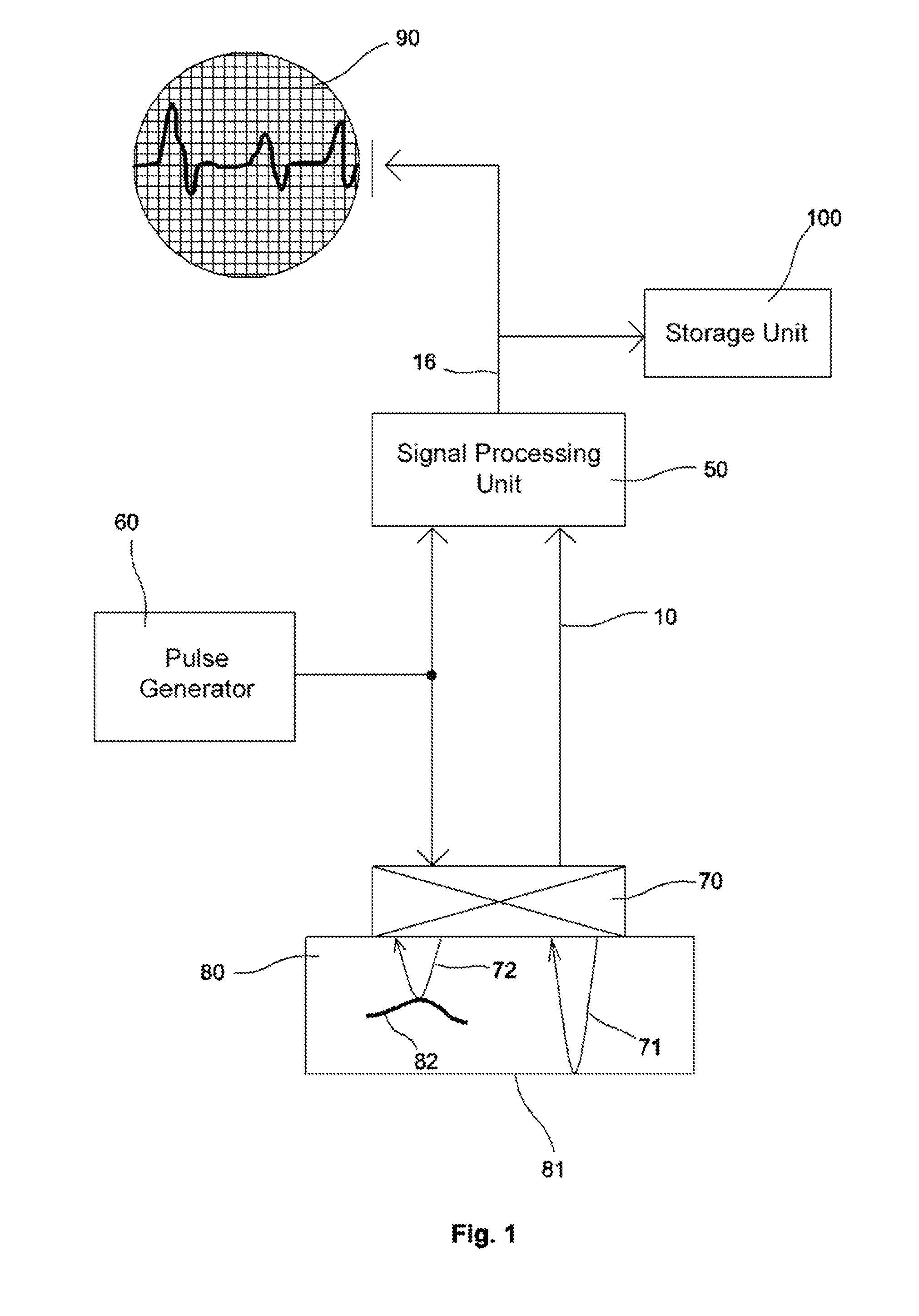
[0053]Following this signal processing, the generated output signal 16 can be displayed on a display 90, such as an oscilloscope, and / or stored in a storage unit 100. Due to the completed compensation of the direct-current offset, the ratio S / N of wanted signals to unwanted signals is increased as compared with solutions without any com...


PUM

PropertyMeasurementUnit
direct-currentaaaaaaaaaa
ultrasonicaaaaaaaaaa
threshold analysisaaaaaaaaaa

Abstract

The invention relates to a method for processing an ultrasonic analog signal (10) representing a reflected ultrasonic wave, wherein the ultrasonic analog signal (10) is fed in a parallel manner into at least two signal paths (A;B) and the ultrasonic analog signal is supplied in each signal path (A;B) to respective amplifiers (20A;20B) whose gains are different from one another. The ultrasonic analog signals (11;11′) which have thus been amplified differently are supplied in each signal path (A;B) to a respective A / D converter (30A;30B) which converts the amplified ultrasonic analog signals (11; 11′) into digital ultrasonic data (12;12′), from which a combined digital ultrasonic signal (15) is reconstructed after further processing steps. According to the invention, a decomposition of the digital ultrasonic data (12; 12′) is carried out in each signal path (A;B) by the first level of a wavelet filter algorithm, and the wavelet coefficients are altered by a threshold analysis. A combined digital ultrasonic signal (15) is then reconstructed from the ultrasonic data thus decomposed, wherein an inverse transformation of the combined ultrasonic signal (15) is carried out by the second level of the wavelet filter algorithm with the altered wavelet coefficients. The invention moreover relates to an associated signal processing unit and an ultrasonic inspection device comprising such a signal processing unit.

Description

FIELD OF THE INVENTION[0001]Embodiments of the present invention relate to a method for processing an ultrasonic analog signal representing an ultrasonic wave reflected in an inspected object.[0002]Embodiments of the present invention also relate to an associated signal processing unit and an ultrasonic inspection device using such a signal processing unit.BACKGROUND OF THE INVENTION[0003]A variety of methods for the non-destructive inspection of a test object by means of ultrasound are known from the field of material testing. In the pulse echo methods, a short ultrasonic pulse generated by an ultrasonic transmitter (transducer) is suitably insonified into a test object so that it propagates in the test object. If the pulse hits a flaw in the test object, for example a discontinuity, the pulse is reflected at least partially. The reflected pulse is detected by means of an ultrasonic receiver. The position of the discontinuity in the test object can be deduced from the travel time b...

Claims


Application Information

Patent Timeline
Patent Type & Authority Applications(United States)
IPC IPC(8): G01N29/44G01N29/46G06F17/14
CPCG01N29/4445G01N29/46G06F17/148G01N2291/044
Inventor KOCH, ROMAN HEINRICHFINGER, GERHARDBUSCH, KLAUS-PETER
Owner GE SENSING & INSPECTION TECH GMBH
Why Eureka
Try Eureka