Variable magnification device and telescopic sight using the same

a magnification device and telescopic technology, applied in the field of variable magnification devices and telescopic sight using the same, can solve the problems of affecting the alignment of the line of sight of the shooter, the distortion of the aiming posture, and the narrow field of vision, so as to improve prevent the distortion of the aiming posture, and easily and finely adjust the magnification of the telescopic sight

Active Publication Date: 2014-01-07
LIM DO HYEON
View PDF4 Cites 2 Cited by
  • Summary
  • Abstract
  • Description
  • Claims
  • Application Information

AI Technical Summary

Benefits of technology

[0023]In the light of the above circumstances, it is an object of the present invention to provide a variable magnification device which is capable of easily adjusting a magnification of a telescopic sight with one hand of a shooter in an aiming posture where a rifle is put on a shoulder of the shooter, and a telescopic sight using the same.
[0024]It is another object of the present invention to provide a variable magnification device which is capable of easily adjusting a focus of a telescopic sight, and a telescopic sight using the same.
[0031]The present invention has an advantage in that the magnification of the telescopic sight can be adjusted with an aiming posture maintained, thereby allowing immediate hit on a target.
[0032]The present invention has another advantage in that a leverage effect can be used to easily and finely adjust the magnification of the telescopic sight with one hand, thereby preventing distortion of an aiming posture as maximally as possible.
[0033]The present invention has another advantage in that the rod provided to apply the leverage effect can be bent and laid down along the barrel of the telescopic sight for easy receipt.

Problems solved by technology

However, since the front sight and the back sight are very small and their alignment may be in disorder due to small shaking, a shooter requires extreme concentration for alignment of the line of sight.
In addition, as the shooter is excessively concerned about the alignment of the line of sight, the shooter's eyes are focused on the front sight and the back sight rather than the target and forward situations, which results in a narrow field of vision.
In addition, the line-of-sight alignment takes a relatively long time, which is against the nature of shooting that a secured target has to be instantaneously hit.
However, it is difficult for the zoom front wheel 27 to be rotated at an aiming posture.
This is because it is not easy to find a position of the zoom front wheel 27 only with the feel of hands at the aiming posture at which the eye is concentrated on the inside of the ocular barrel 30.
In addition, it is difficult for the zoom front wheel 27 to turn with one hand since it is stiffly mounted such that it is not randomly rotated by shooting vibration of the rifle.
Moreover, the zoom front wheel 27 has to be finely turned with one hand for an elaborate focus adjustment, which is not an easy work in the aiming posture.

Method used


Image

  • Variable magnification device and telescopic sight using the same
  • Variable magnification device and telescopic sight using the same
  • Variable magnification device and telescopic sight using the same

Examples


Embodiment Construction

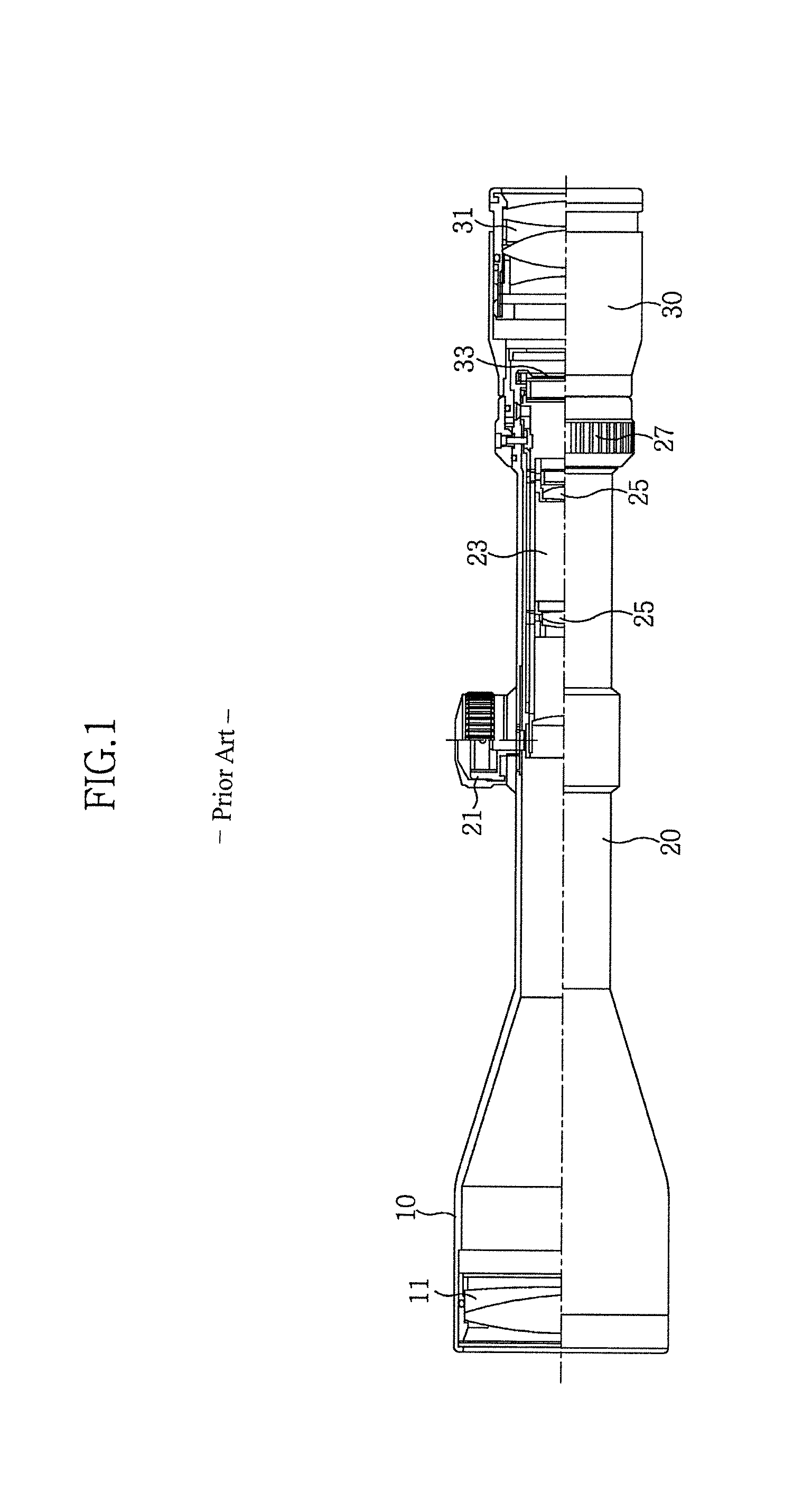
[0042]Hereinafter, preferred embodiments of the present invention will be described in detail with reference to the accompanying drawings. In the following detailed description of the present invention, concrete description on related functions or constructions which was shown in FIG. 1 will be omitted if it is deemed that the functions and / or constructions may unnecessarily obscure the gist of the present invention.

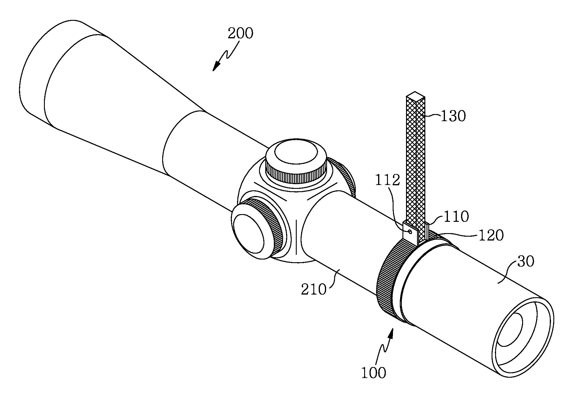
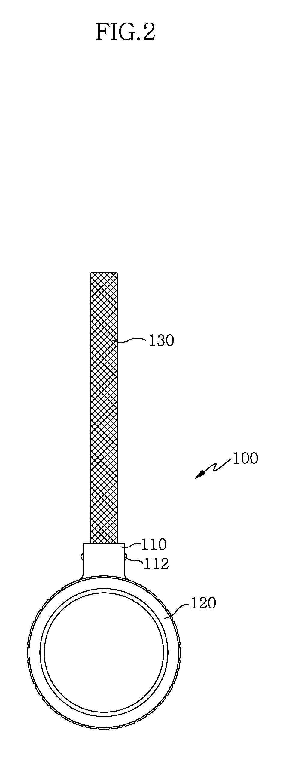
[0043]As shown in FIG. 2, a variable magnification device100 includes a rotation bunch 120 having a bent end 110 placed at one side of its circumference, and a rod 130 connected to the bent end 110.

[0044]As shown in FIG. 3, in the variable magnification device 100, a zoom front wheel 27 is combined at the same position as the conventional zoom front wheel 27 in a barrel of a telescopic sight 200.

[0045]Accordingly, when the rotation bunch 120 is rotated, a zoom lens 25 within a barrel 210 is horizontally moved.

[0046]In this case, the rod 130 acts as a handle to rotate the...


PUM


Abstract

The present invention relates to a variable magnification device and a telescopic sight using the same, and more particularly, to a variable magnification device which is capable of easily adjusting a magnification of a telescopic sight. The variable magnification device includes: a rotation bunch which has a ring shape conforming to the circumference of a barrel of a telescopic sight and includes a bent end formed on one side of the circumference of the rotation bunch; and a rod which is connected to the bent end and is bendable in the longitudinal direction of the barrel. The magnification of the telescopic sight can be adjusted with an aiming posture maintained, thereby allowing immediate hit on a target. In addition, a leverage effect can be used to easily and finely adjust the magnification of the telescopic sight with one hand, thereby preventing distortion of an aiming posture as maximally as possible.

Description

CROSS-REFERENCE TO RELATED APPLICATION[0001]This application claims the benefit of Korean Application No. 10-2010-0041935, filed on May 4, 2010, with the Korean Intellectual Property Office, the disclosure of which is incorporated herein by reference.BACKGROUND OF THE INVENTION[0002]1. Field of the Invention[0003]The present invention relates to a variable magnification device and a telescopic sight using the same, and more particularly, to a variable magnification device which is capable of easily adjusting a magnification of a telescopic sight under a condition where a shooter aims for a target with a telescopic sight, and a telescopic sight using the same.[0004]2. Description of the Related Art[0005]A telescopic sight refers to a sighting telescope which is a device which magnifies and aims for a remote target precisely with it attached to a firearm such as a rifle[0006]As used therein, the term “rifle” refers to a personal firearm which has a bored barrel loaded with bullets, sh...

Claims


Application Information

Patent Timeline
Patent Type & Authority Patents(United States)
IPC IPC(8): F41G1/00G02B23/16G02B7/10G02B7/04F41G1/38G02B7/02F41G1/16
CPCF41G1/38G02B7/10G02B7/04F41G1/00F41G1/16G02B23/16G02B23/00
Inventor LIM, DO, HYEON
Owner LIM DO HYEON
Why Eureka
Try Eureka