Check patentability & draft patents in minutes with Patsnap Eureka AI!

Apparatus and methods for cooling platform regions of turbine rotor blades

a technology of turbine rotor blades and cooling apparatus, which is applied in the direction of mechanical apparatus, machines/engines, manufacturing tools, etc., can solve the problems of low-cycle fatigue cracking, oxidation, creep,

Active Publication Date: 2014-01-14
GE INFRASTRUCTURE TECH INT LLC
View PDF6 Cites 5 Cited by
  • Summary
  • Abstract
  • Description
  • Claims
  • Application Information

AI Technical Summary

Benefits of technology

Enhances cooling efficiency, reduces manufacturing costs, and provides flexibility in cooling distribution, while preventing hot gas ingestion and improving durability of the rotor blades.

Problems solved by technology

In operation, the rotational velocity of the turbine induces mechanical loading that creates highly stressed regions along the platform 110 that, when coupled with high temperatures, ultimately cause the formation of operational defects, such as oxidation, creep, low-cycle fatigue cracking, and others.
These defects, of course, negatively impact the useful life of the rotor blade 100.
However, as one of ordinary skill in the art will appreciate, the platform region 110 presents certain design challenges that make it difficult to cool in this manner.
This adds a great degree of difficulty and complexity to installation and pre-installation flow testing.
A second disadvantage is that the integrity of the cavity 119 formed between adjacent rotor blades 100 is dependent on how well the perimeter of the cavity 119 is sealed.
Inadequate sealing may result in inadequate platform cooling and / or wasted cooling air.
A third disadvantage is the inherent risk that hot gas path gases may be ingested into the cavity 119 or the platform itself 110.
However, conventional designs of this nature have several limitations or drawbacks.
First, as illustrated, only a single circuit is provided on each side of the airfoil 102 and, thus, there is the disadvantage of having limited control of the amount of cooling air used at different locations in the platform 110.
Second, conventional designs of this type have a coverage area that is generally limited.
Third, to obtain better coverage with intricately formed platform cooling channels 120, manufacturing costs increase dramatically, particularly if the cooling channels having shapes that require a casting process to form.
Fourth, these conventional designs typically dump coolant into the hot gas path after usage and before the coolant is completely exhausted, which negatively affects the efficiency of the engine.
Fifth, conventional designs of this nature generally have little flexibility.
In addition, these types of conventional designs are difficult to repair or refurbish.
In addition, as one of ordinary skill in the art will appreciate, another challenge associated with these types of cooling arrangements is the connection that is often required between the platform cooling circuit, i.e., the cooling passages formed through the interior of the platform, and the main cooling circuit, i.e., the interior cooling passages formed through the interior of the root and airfoil.
As such, forming the connection as part of a post-cast machining process may create stress concentrations that are unacceptable.
However, forming the connection as part of the casting process requires that the core of the platform cooling circuit must be connected to the core of the main cooling circuit during the casting process, which typically is not desirable.
This movement, while acceptable for the placement of the main cooling circuit, makes it difficult to satisfy the tight placement tolerances of the platform cooling circuit if the movement of the main core is translated to the platform core.
Conventional platform cooling designs fail to satisfy these important requirements.

Method used


Image

  • Apparatus and methods for cooling platform regions of turbine rotor blades
  • Apparatus and methods for cooling platform regions of turbine rotor blades
  • Apparatus and methods for cooling platform regions of turbine rotor blades

Examples


Embodiment Construction

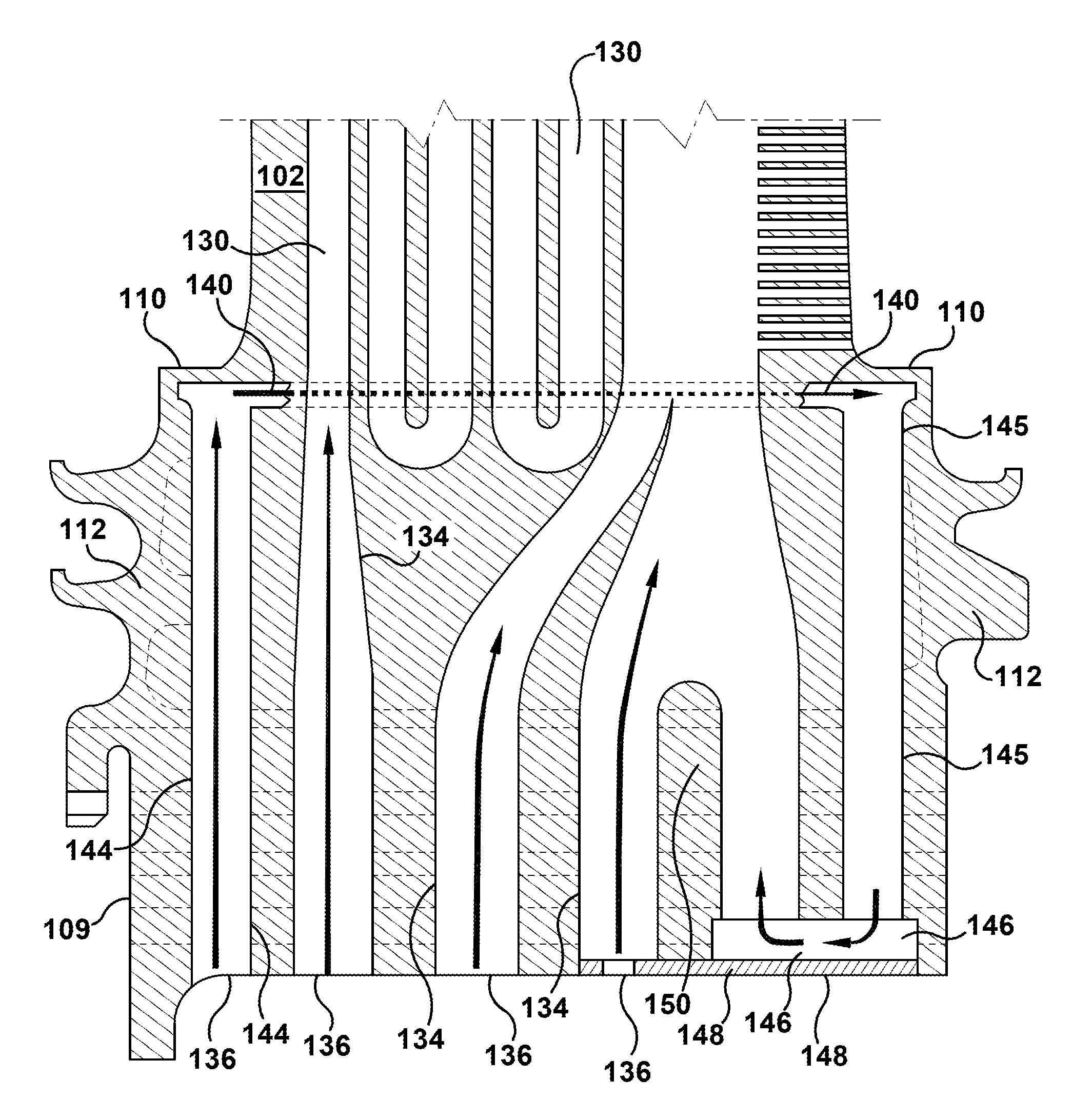
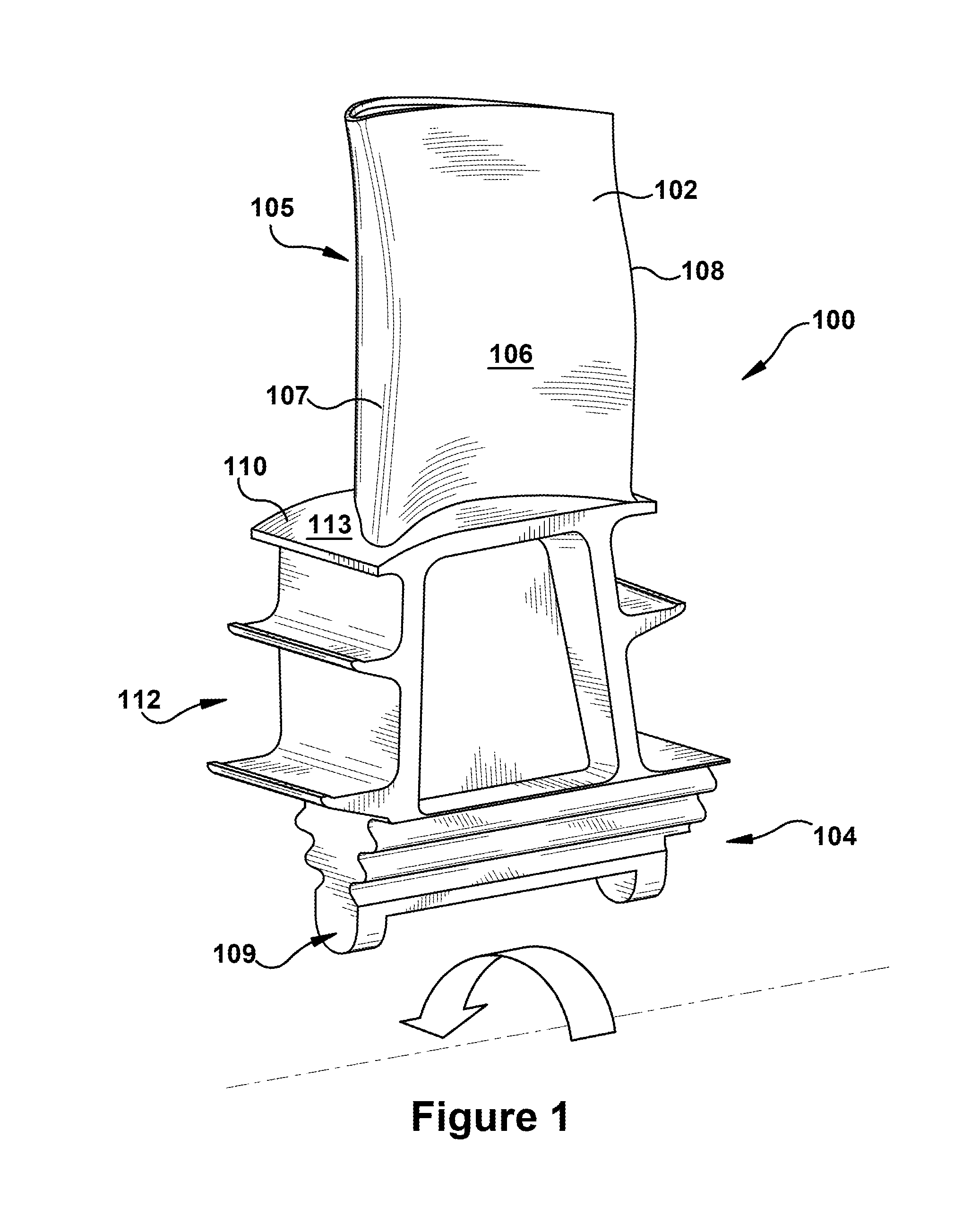
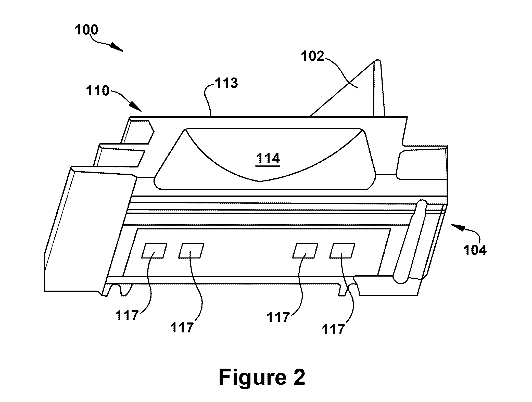
[0031]Referring now to FIGS. 6 through 13, several embodiments of the present invention are provided. As shown in FIG. 6, the present invention may include a configuration of cooling channels through the interior of a turbine rotor blade 100. The present invention may be employed in a turbine rotor blade having a platform 110 at the interface between an airfoil 102 and a root 104. It will be appreciated that, along an inner radial portion, the root 104 may comprise a mechanical attachment that is configured to engage a turbine wheel. Typically, the mechanical attachment is a dovetail 109 that inserts into a slot formed in the turbine wheel. Along an outer radial portion, the root 104 generally includes a shank 112 that extends between the dovetail 109 and the platform 110.

[0032]The turbine rotor blade 100 also may include an airfoil cooling channel 130. The airfoil cooling channel 130 may include an interior channel that directs or channels coolant through any portion of the airfoil...


PUM

PropertyMeasurementUnit
distanceaaaaaaaaaa
radial heightaaaaaaaaaa
mechanical energyaaaaaaaaaa

Abstract

A configuration of cooling channels through the interior of a turbine rotor blade having a platform, wherein the rotor blade includes an airfoil cooling channel that includes a cooling channel formed within the airfoil and an outboard airfoil supply channel. The configuration of cooling channels may include: a platform cooling channel that comprises a cooling channel that traverses at least a portion of the platform, the platform cooling channel having an upstream end and a downstream end; an outboard platform supply channel, which comprises a cooling channel that stretches from a second coolant inlet formed in the root to the upstream end of the platform cooling channel; and an inboard platform return channel, which comprises a cooling channel that stretches from the downstream end of the platform cooling channel to a termination point formed in the root.

Description

BACKGROUND OF THE INVENTION[0001]The present application relates generally to combustion turbine engines, which, as used herein and unless specifically stated otherwise, includes all types of combustion turbine engines, such as those used in power generation and aircraft engines. More specifically, but not by way of limitation, the present application relates to apparatus, systems and / or methods for cooling the platform region of turbine rotor blades.[0002]A gas turbine engine typically includes a compressor, a combustor, and a turbine. The compressor and turbine generally include rows of airfoils or blades that are axially stacked in stages. Each stage typically includes a row of circumferentially spaced stator blades, which are fixed, and a set of circumferentially spaced rotor blades, which rotate about a central axis or shaft. In operation, the rotor blades in the compressor are rotated about the shaft to compress a flow of air. The compressed air is then used within the combust...

Claims


Application Information

Patent Timeline
Patent Type & Authority Patents(United States)
IPC IPC(8): F01D5/08
CPCY02T50/676F01D5/18F01D5/081F05D2240/81Y02T50/60Y10T29/49988Y10T29/49989Y10T29/49341
Inventor BOYER, BRADLEY, TAYLOR
Owner GE INFRASTRUCTURE TECH INT LLC
Features
  • R&D
  • Intellectual Property
  • Life Sciences
  • Materials
  • Tech Scout
  • Unparalleled Data Quality
  • Higher Quality Content
  • 60% Fewer Hallucinations
Learn More