Heat pump system and heat pump operation method

a heat pump and heat pump technology, applied in mechanical equipment, machines/engines, lighting and heating apparatus, etc., can solve the problems of compressor not being able to start up, steam discharged from the compressor not being directly supplied to the external heat-utilizing facility,

Inactive Publication Date: 2009-05-21
HITACHI LTD
View PDF8 Cites 46 Cited by
  • Summary
  • Abstract
  • Description
  • Claims
  • Application Information

AI Technical Summary

Benefits of technology

[0009]An object of the present invention is to provide a compact heat pump system and a heat pump operation method, which can avoid the occurrence of surging in a compressor at startup of a heat pump and can directly supply vapor of working medium produced by the compressor to an external heat-utilizing facility.
[0012]According to the present invention, the compact heat pump system and the heat pump operation method are realized which can avoid the occurrence of surging in the compressor at startup of the heat pump and can directly supply the vapor of the working medium produced by the compressor to the external heat-utilizing facility.

Problems solved by technology

In other words, steam discharged from the compressor is not directly supplied to the external heat-utilizing facility.
In the case of the compressor being of the turbo type, such a condition gives rise to a phenomenon that the compressor cannot be started up due to the occurrence of surging.

Method used


Image

  • Heat pump system and heat pump operation method
  • Heat pump system and heat pump operation method
  • Heat pump system and heat pump operation method

Examples


first embodiment

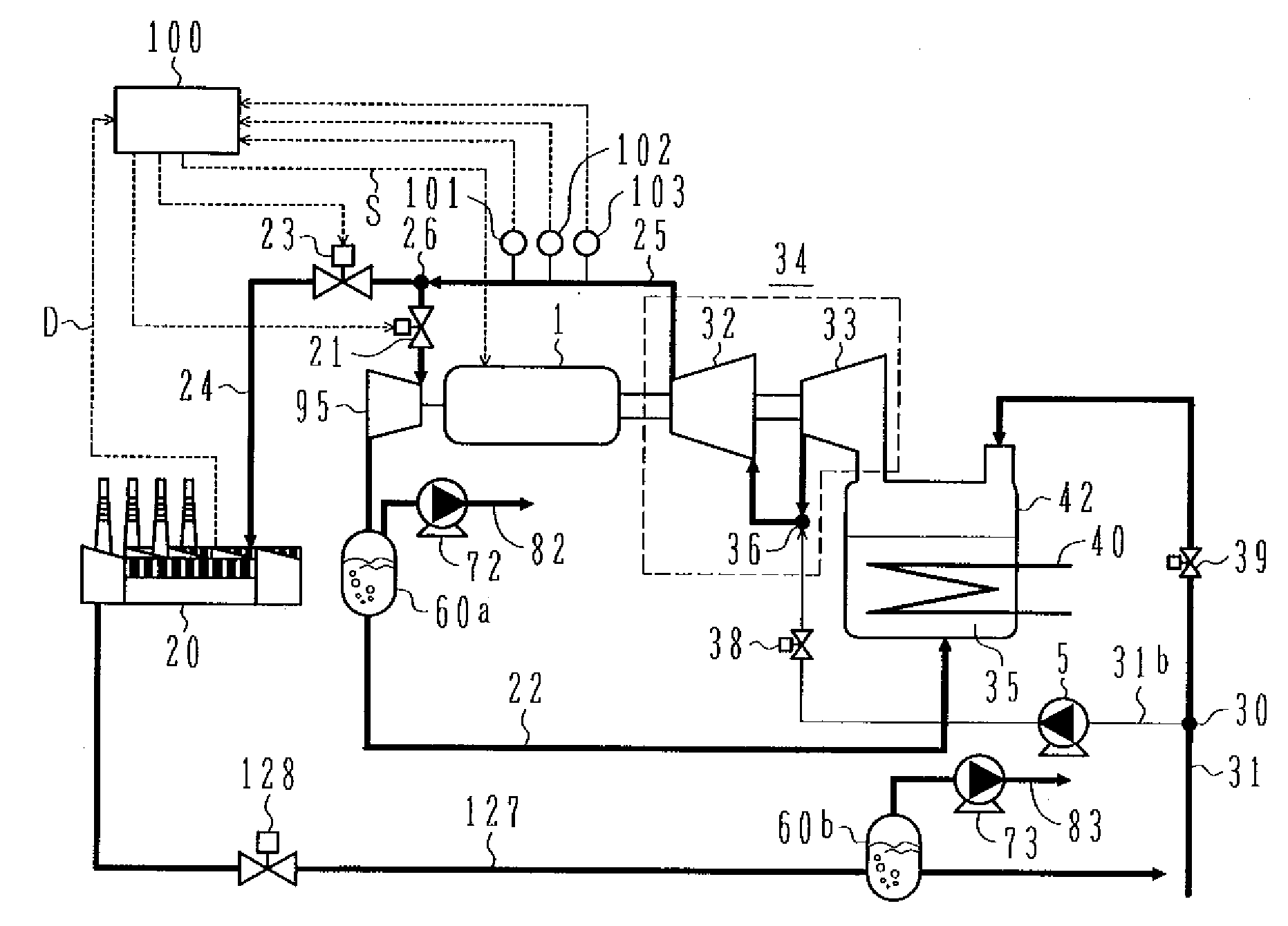
[0019]A heat pump system according to a first embodiment of the present invention will be described in detail below with reference to FIG. 1.

[0020]The heat pump system according to the first embodiment of the present invention comprises an evaporator 42 for evaporating liquid water 35 stored therein as a working medium through heat exchange with a high-temperature heat source, which is supplied from the exterior, and for producing water vapor (steam), i.e., vapor of the working medium, a compression unit 34 driven by a motor 1, i.e., a driving unit, and pressurizing the water vapor produced by the evaporator 42 to high-temperature steam, the motor 1 for driving the compression unit 34, a discharge piping line 25 for supplying the high-temperature steam pressurized by the compression unit 34, and a return piping line 22 for introducing the steam or liquid water from the compression unit 34 to the evaporator 42. In the heat pump system, the high-temperature steam pressurized and produ...

second embodiment

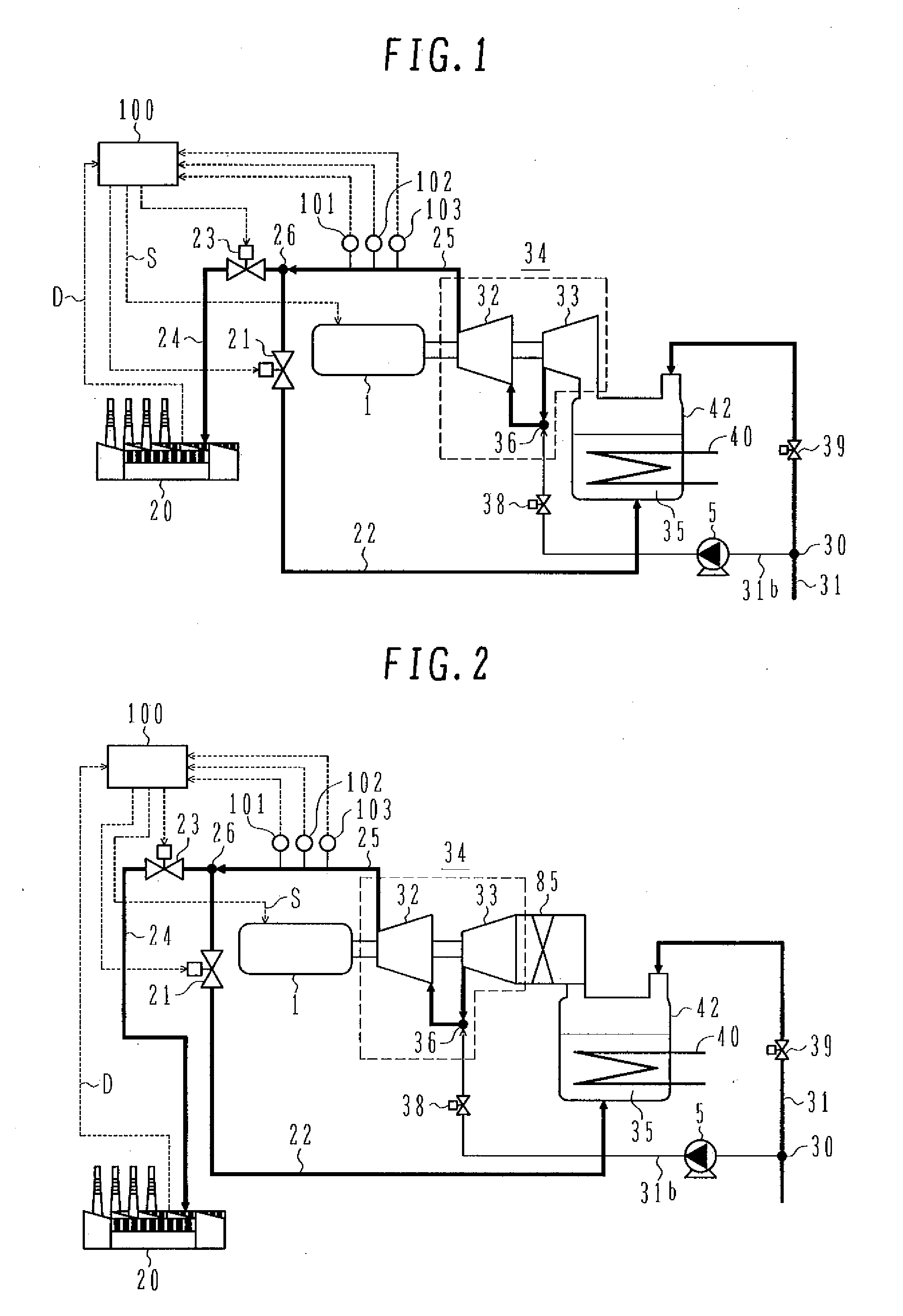
[0047]A heat pump system according to a second embodiment of the present invention will be described below with reference to FIG. 3. Since the heat pump system according to this second embodiment has the same basic construction as that of the heat pump system according to the first embodiment shown in FIG. 1, the common construction and operation and the status variables of the working medium are not described here and the following description is made of only different points.

[0048]In this second embodiment shown in FIG. 3, as the driving unit for the compressors 32 and 33, a steam turbine 2 coupled to the compressors 32 and 33 through a rotor is used instead of a motor. Also, the evaporator is constituted as an evaporator 42b employing a plate-type heat exchanger allowing passage of a two-phase flow therein instead of the heat exchanger having piping in the form of tubes.

[0049]The steam turbine 2 is driven in accordance with the control signal S from the control unit 100 to rotate...

third embodiment

[0059]A heat pump system according to a third embodiment of the present invention will be described below with reference to FIG. 4. Since the heat pump system according to this third embodiment has the same basic construction as that of the heat pump system according to the first embodiment shown in FIG. 1, the common construction and operation and the status variables of the working medium are not described here and the following description is made of only different points.

[0060]In the heat pump system according to this third embodiment shown in FIG. 4, a cooler 50 is installed midway a return piping line 22b, which is branched from the discharge piping line 25 at the branch point 26 and connected with the water feed line 31 for supplying water, i.e., the working medium in liquid phase, to the evaporator 42, with a cooling water line 51 partly disposed in the cooler 50. In the cooler 50, the steam discharged from the first-stage compressor 33 and the second-stage compressor 32 con...


PUM


Abstract

A compact heat pump system and a heat pump operation method, which can avoid the occurrence of surging in a compressor at startup of a heat pump and can directly supply vapor of a working medium produced by the compressor to an external heat-utilizing facility. The heat pump system comprises an evaporator for recovering heat of an external heat source to a working medium supplied as liquid water from the exterior via a water feed channel, thereby evaporating the working medium, a compressor for compressing the working medium evaporated in the evaporator and increasing temperature of the evaporated working medium, and a driving unit for giving motive power to drive the compressor. The heat pump system further comprises a supply channel for supplying, as a heat source, vapor of the working medium having temperature increased by the compressor to an external heat-utilizing facility, and a return channel branched from the supply channel and introducing the working medium discharged from the compressor to the evaporator.

Description

[0001]This application is a continuation of application Ser. No. 11 / 476,707 filed on Jun. 29, 2006 which claims priority to Japanese Application No. 2005-192488 filed on Jun. 30, 2005.BACKGROUND OF THE INVENTION[0002]1. Field of the Invention[0003]The present invention relates to a heat pump system for supplying heat. More particularly, the present invention relates to a heat pump system utilizing vapor (steam) as a heat source for supply to the exterior and a heat pump operation method.[0004]2. Description of the Related Art[0005]A heat pump system employing a turbo compressor, which is operated by using water as a working medium, has already been practiced to supply a low-temperature heat source and utilized in air conditioning systems, etc. For example, JP,A 2001-165514 (Patent Document 1) discloses a technique of integrally packaging an evaporator, a condenser, a compressor, and a compressor driving motor in one enclosed vessel.[0006]Also, JP,A 63-231150 (Patent Document 2) disc...

Claims


Application Information

Patent Timeline
Patent Type & Authority Applications(United States)
IPC IPC(8): F25B9/00F25B27/00F25B1/00F02C1/04
CPCB01D3/007F22B3/045F01K3/006B01D19/0068Y02P70/10
Inventor SHIBATA, TAKANORIHATAMIYA, SHIGEOFUKUSHIMA, TOSHIHIKO
Owner HITACHI LTD
Why Eureka
Try Eureka