System and method for diffusing gas bubbles into a body of water

a technology of gas bubbles and diffusers, which is applied in the direction of carburetizing air, biological water/sewage treatment, and separation processes, etc., can solve the problems of inability to locate an air releaser, less economic losses, and the diffuser resting on the bottom of the container is quite short, so as to improve aeration and mi, increase the contact time of air bubbles, and reduce energy consumption

Inactive Publication Date: 2000-01-25
BAUGHMAN MICHAEL L +1
View PDF14 Cites 56 Cited by
  • Summary
  • Abstract
  • Description
  • Claims
  • Application Information

AI Technical Summary

Problems solved by technology

It is believed that in the operation of a fish farm, oxygen depletion probably results in more economic losses than all other factors combined.
In all these devices, some of the air is absorbed as the bubbles rise through the water, and the air that is not absorbed escapes from the surface of the water and may or may not be captured for recirculation.
Prior workers in this field who have addressed themselves to the aeration of the water in a fish culture pond have long recognized the problem presented by the fact that the transit time of air bubbles moving up through the water from an air diffuser resting on the bottom of the container is quite short if the container is shallow.
The prior art universally teaches that it is not feasible to locate an aerator that releases air bubbles any deeper in the body of water being treated than necessary because such aerators operate much less efficiently in deep water.
In addition to requiring that a very large portion of the mixed liquor must be below ground at all times, Bailey et al. do not teach the use of fine air bubbles or even of medium size air bubbles.
Because of this latter point, if the length-to-width ratio discussed above is too large, a suitable size diffuser may be too bulky for the width of the basin.

Method used


Image

  • System and method for diffusing gas bubbles into a body of water
  • System and method for diffusing gas bubbles into a body of water
  • System and method for diffusing gas bubbles into a body of water

Examples


example 1

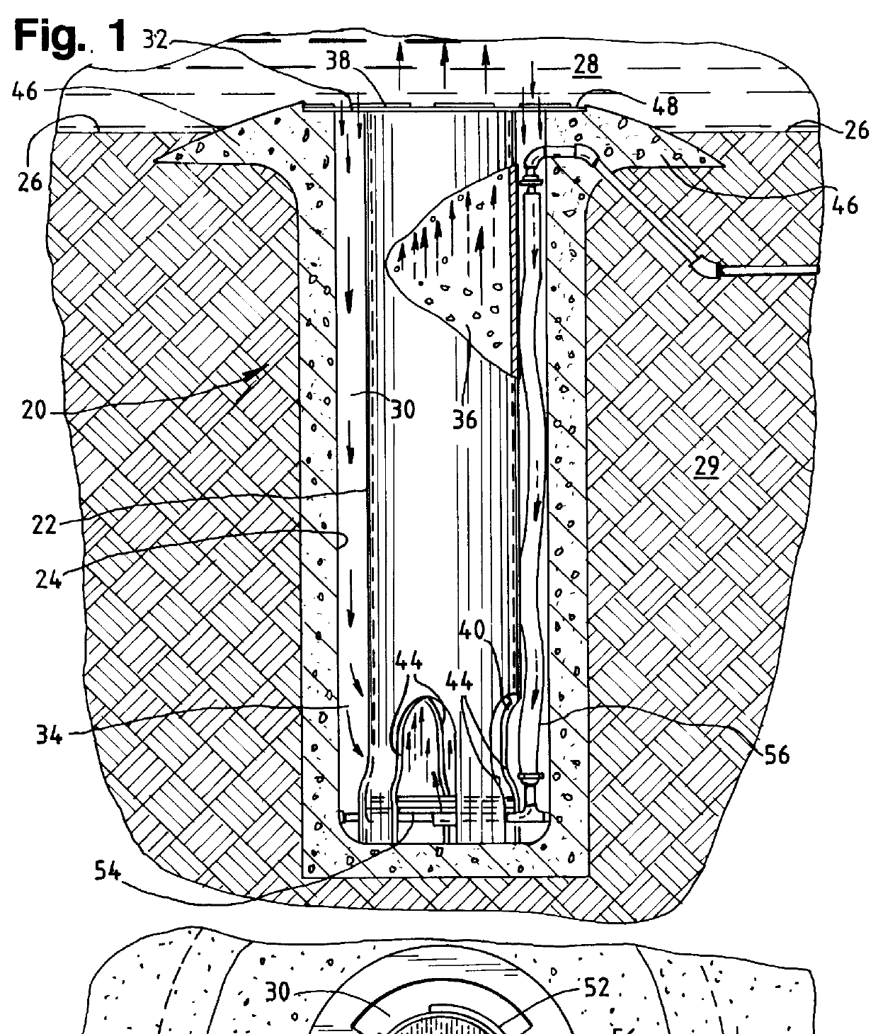
In this Example, two counterflow air lift diffusers generally similar to the diffuser shown in FIG. 1 of the accompanying drawing were installed at points approximately one-third and two-thirds, respectively, along the longitudinal center line of a pond having about 0.7 surface acre and an average depth of about 4 feet. The pond was generally rectangular in plan, with an average length of about 300 feet and an average width of about 100 feet.

FIG. 15 gives a longitudinal cross section of the pond 320 and of its end walls 322 and bottom wall 324, with the two counterflow air lift diffusers installed below ground in the approximate positions just described, near the middle part of the pond.

The outer cylinder of each counterflow air lift diffuser was constructed of polyvinyl chloride pipe having an inside diameter of about 111 / 2 inches. The inner cylinder was formed of the same material, with an inside diameter of about 8 inches and an outside diameter of about 81 / 2 inches. The outer cy...

example 2

In this Example, counterflow air lift diffusers generally similar to the diffuser used in Example 1, except that they had downflow and return channels that were each about 10' deep, were installed in each of five ponds. Three of the ponds were smaller than the other two.

Two counterflow air lift diffusers were installed in each of the three smaller ponds, at points equally spaced along the longitudinal center line of the pond. Four units were installed in each of the two larger ponds, at points equally spaced along the longitudinal center line of each of these ponds. The resulting installation of diffusers in each of the smaller ponds was approximately the same (except for the depth of the downflow and return channels) as that shown in FIG. 15 for Example 1.

The surface areas of the five ponds varied from approximately 0.68 acre to approximately 1.06 acres. Each pond had an average depth of about 4 feet.

As in Example 1, during the approximately 90-day test period of this Example, each...

example 3

The system of this Example is used for the treatment of the water in a fish culture pond that contains an unusually high level of fish in terms of pounds of fish per cubic foot of water, i.e., approximately 1 lb. per cubic foot.

The system used in this Example is similar to the system of Example 1, except that (1) the pond is only about 4' deep, with a resulting volume of about 52,270 cubic feet, and (2) only 3 counterflow air lift diffusers are installed in a regular pattern below the bottom of the pond.

This latter fact makes the total below-ground volume for all three counterflow air lift diffusers taken together approximately 52.0 cubic feet. Thus, the volume of the body of water being treated is approximately 1,005 times the total volume of the space occupied by the water that at any given time is flowing through the below-ground channels of all 3 diffusers used in this Example.

When the system of this Example is used in a fish culture pond, adequate levels of oxygen are present f...


PUM

PropertyMeasurementUnit
distanceaaaaaaaaaa
distanceaaaaaaaaaa
lengthaaaaaaaaaa

Abstract

System and method for diffusing gas bubbles into a pond, lagoon or basin that is used for fish farming or other form of aquaculture. A small amount of water is continuously removed from the bottom of the body of water by one or more counterflow gas lift diffusers. This small amount of water is flowed down underground, has gas bubbles introduced into it, and is then returned to the body of water. The quantity of water removed and treated in this way is a small fraction of the total body of water in the pond, lagoon or basin. The ratio of (1) the total volume of the channels below ground through which the water flows downward, and then back up into the body of water, to (2) the volume of the body of water above ground is at all times less than about 1:100. In the broadest form of the invention, a gas diffuser introduces gas bubbles into the water in the return channel at a level at least about 2 feet below the bottom of the body of water, and no more then about 50 feet below the surface of the body of water being treated. The downflow and return channels and the space joining them at their bottom ends extend no more than about 50 feet below the surface of the water being treated.

Description

This invention relates to a system and a method for diffusing gas bubbles into a body of water that is employed in an aqualculture operation and is substantially confined--as, for example, in a pond, lagoon, tank or other basin--against lateral movement in any direction around its entire perimeter. The invention results in an increase in the gas-liquid contact time, and also an increase in the degree of regasification effected at the surface of the water. Both of these increases significantly improve the gas transfer efficiency for the bubbles that are being introduced into the water.BACKGROUND OF INVENTIONThis invention may be used in the diffusion into a body of water of gas bubbles of any type, and has particular relevance to the diffusion into water of bubbles of air or of pure oxygen. In every case, the principal purpose for which the invention is used is to increase the rate at which a gas is absorbed by a body of water.Aeration or oxygenation is very important in the operatio...

Claims


Application Information

Patent Timeline
Patent Type & Authority Patents(United States)
IPC IPC(8): B01F3/04C02F7/00B01F7/00C02F3/20C02F3/22
CPCB01F3/04106B01F3/04468B01F3/0451B01F3/04517B01F3/04531B01F3/04539B01F3/04609C02F3/20C02F3/223C02F7/00B01F7/00341B01F2003/04546B01F2003/04673Y02W10/10B01F23/231B01F23/2321B01F23/23231B01F23/232311B01F23/233B01F23/23311B01F23/23341B01F23/2331B01F23/23362B01F27/113
Inventor BAUGHMAN, MICHAEL L.HORNER, ADMINISTRATOR, BRENTON L.
Owner BAUGHMAN MICHAEL L
Why Eureka
Try Eureka