
Multi-junction solar cells with a homogenizer system and coupled non-imaging light concentrator

a solar cell and homogenizer technology, applied in solar heat systems, solar thermal energy generation, lighting and heating apparatus, etc., can solve the problems of limited utility, low efficiency, and low efficiency of solar cells for electrical energy production, and achieve high efficiency and moderate irradiance non-uniformity

Inactive Publication Date: 2014-01-21
LIGHT PRESCRIPTIONS INNOVATORS
View PDF171 Cites 9 Cited by
  • Summary
  • Abstract
  • Description
  • Claims
  • Application Information

AI Technical Summary

Benefits of technology

The solution results in a highly efficient electrical output with moderate irradiance non-uniformity, enabling the solar cell system to operate effectively at higher concentration levels without abrupt efficiency drops, thus improving competitiveness with other energy sources.

Problems solved by technology

Solar cells for electrical energy production are very well known but have limited utility due to the very high Kwh cost of production.
While substantial research has been ongoing for many years, the cost per Kwh still is about ten times that of conventional electric power production.
This system has a clear limitation in that the illumination on the solar cell it can achieve is highly non-uniform, which reduces the cell efficiency and system reliability.
This concentration value cannot be tolerated by present high-efficiency multifunction cells, which show an abrupt drop in efficiency if they operate above 2,000-3,000 suns.
The concentration-acceptance angle product that can be attained with this configuration is very limited, because the numerical aperture on the cell is small.
Additionally, the system cannot be compact because the optic is refractive and uses a single Kohler integration element.

Method used


Image

  • Multi-junction solar cells with a homogenizer system and coupled non-imaging light concentrator
  • Multi-junction solar cells with a homogenizer system and coupled non-imaging light concentrator
  • Multi-junction solar cells with a homogenizer system and coupled non-imaging light concentrator

Examples


Embodiment Construction

[0027]This invention makes use of the invention, including embodiments and design methods, described in U.S. Provisional Application No. 60 / 703,667 titled “Free-Form Lenticular Optical Elements and their Application to Condensers and Headlamps”, filed Jul. 28, 2005 by some of the present inventors, which is incorporated herein by reference in its entirety.

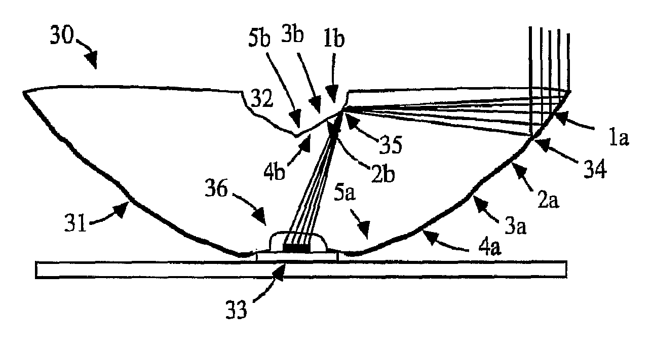
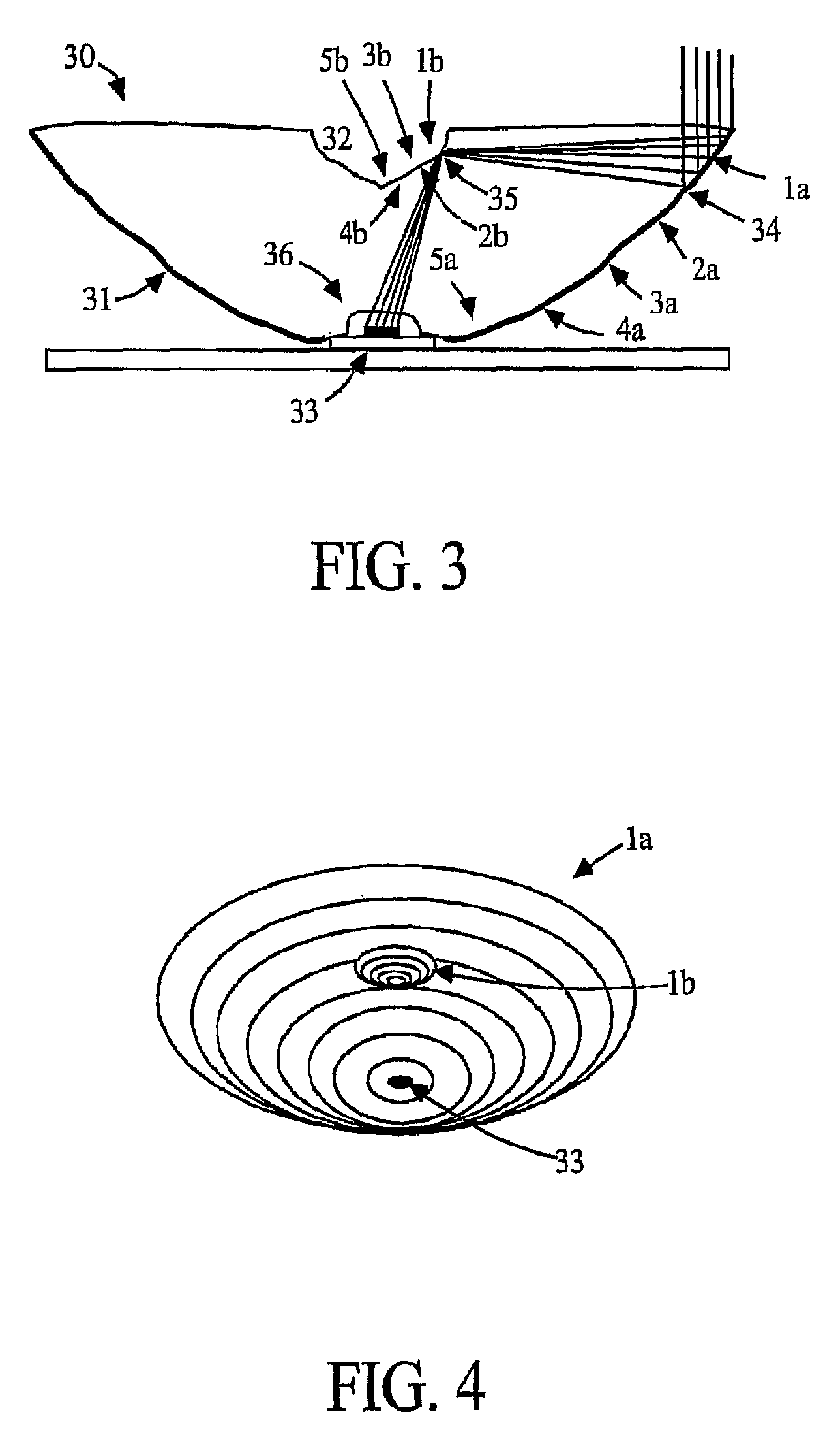
[0028]An optical system constructed in accordance with one embodiment of the invention is shown in FIG. 3 as a most preferred embodiment. The entrance aperture 30 and the exit aperture 36 can be flat. Segmented secondary mirror 32 is substantially co-planar with the entrance aperture 30 of a primary mirror 31. The segments on the primary 1a, 2a, etc. are essentially parabolic, each with a focus at the associated mirror segment 1b, 2b, etc. on the secondary and along the vertical axis (not shown). The secondary mirror segments 1b, 2b, etc. are essentially elliptical with foci at the locations of the associated primary mirror segment...


PUM


Abstract

The present embodiments provide methods and systems to homogenize illumination on a target. Some embodiments provide rotational symmetric dual-reflector solar concentrators that include a concave primary reflector with an aim-direction directed toward the sun to receive optical radiation in a far-field angle within an angle of acceptance and redirect radiation upward and centrally generating flux concentration, a secondary reflector positioned coaxial with said primary reflector to receive said redirected radiation and redirect radiation downward and centrally generating flux concentration solar rays, and a central target zone receiving said concentrated solar rays, where cross sections of said primary and secondary reflectors both further comprise a multiplicity of segments that establish a correspondence between pairs of segments, each of said segments of said primary reflector such as to image said angle of acceptance onto said corresponding segment of said secondary reflector to image onto said target zone.

Description

PRIORITY CLAIM[0001]This application is a continuation of International Application No. PCT / US2007 / 063522, filed Mar. 7, 2007 and entitled “MULTI-JUNCTION SOLAR CELLS WITH A HOMOGENIZER SYSTEM AND COPULED NON-IMAGING LIGHT CONCENTRATOR”, which claims the benefit of U.S. Provisional Application No. 60 / 780,520, filed Mar. 8, 2006 and entitled “MULTI-JUNCTION SOLAR CELLS WITH A HOMOGENIZER SYSTEM AND COPULED NON-IMAGING LIGHT CONCENTRATOR”, each of which is incorporated herein by reference in their entirety; and[0002]this application is a continuation-in-part of U.S. patent application Ser. No. 11 / 997,142, filed Jun. 30, 2008 and entitled “FREE-FORM LENTICULAR OPTICAL ELEMENTS AND THEIR APPLICATION TO CONDENSERS AND HEADLAMPS”, which is the National Stage of International Application No. PCT / US2006 / 029464, filed Jul. 28, 2006 and entitled “FREE-FORM LENTICULAR OPTICAL ELEMENTS AND THEIR APPLICATION TO CONDENSERS AND HEADLAMPS”, which claims the benefit of both U.S. Provisional Applicat...

Claims


Application Information

Patent Timeline
Patent Type & Authority Patents(United States)
IPC IPC(8): F24J2/10F24S23/70F24S23/79
CPCF24J2/085F24J2/12F24J2/18H01L31/0547Y02E10/42Y02E10/43Y02E10/52F24S23/31F24S23/71F24S23/79Y02E10/40
Inventor BENITEZ, PABLOMINANO, JUAN CARLOSHERNANDEZ, MAIKELBLEN, JOSEMOHEDANO, RUBENDROSS, OLIVER
Owner LIGHT PRESCRIPTIONS INNOVATORS
Learn More