
Ball bat with internal impact dampening means

a technology of dampening means and ball bats, which is applied in the field of ball bats with internal impact dampening means, can solve the problems of selective limitation of ball bat deformation and decrease of bat performance, and achieve the effects of reducing the trampoline effect, limiting the deformation of ball bats, and maintaining the performance level

Active Publication Date: 2014-01-21
WILSON SPORTING GOODS
View PDF33 Cites 23 Cited by
  • Summary
  • Abstract
  • Description
  • Claims
  • Application Information

AI Technical Summary

Benefits of technology

The present invention provides a new design for a baseball bat that can achieve maximum performance allowed by industry regulatory organizations and maintain that level of performance over a long period of time. This is accomplished by including at least one restriction member that can limit the deformation of the bat upon impact. The restriction member is a resilient object capable of resisting deformation. The staffing of the restriction member can be adjusted depending on different performance restrictions or play styles, allowing for selective control over the deformation of the bat and fine control over its performance. Overall, the present invention provides a high-performance baseball bat design with improved accuracy and consistency.

Problems solved by technology

Restricting the deformation of the barrel limits the trampoline effect, thus decreasing bat performance.
By using a plurality of restriction members with different diameters along the barrel of a ball bat, the deformation of the ball bat may be selectively limited.

Method used


Image

  • Ball bat with internal impact dampening means
  • Ball bat with internal impact dampening means
  • Ball bat with internal impact dampening means

Examples


second embodiment

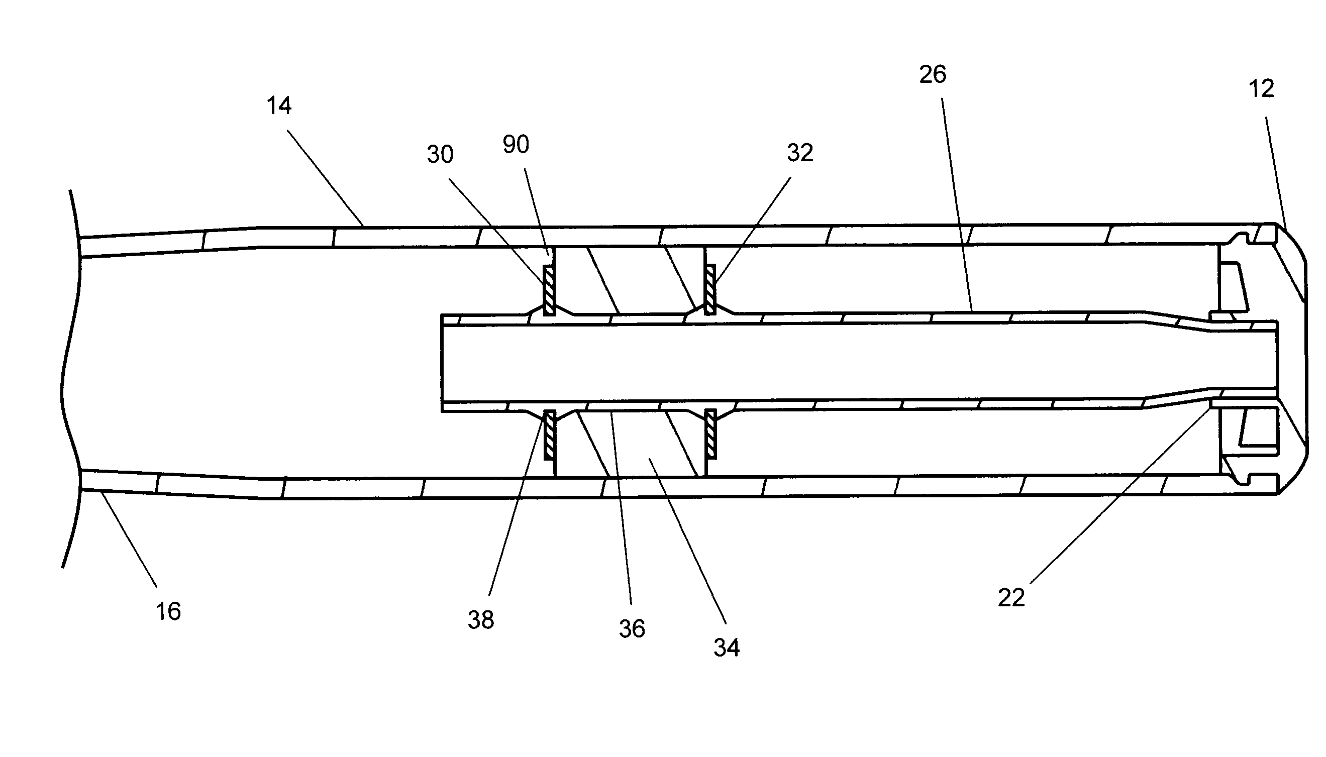
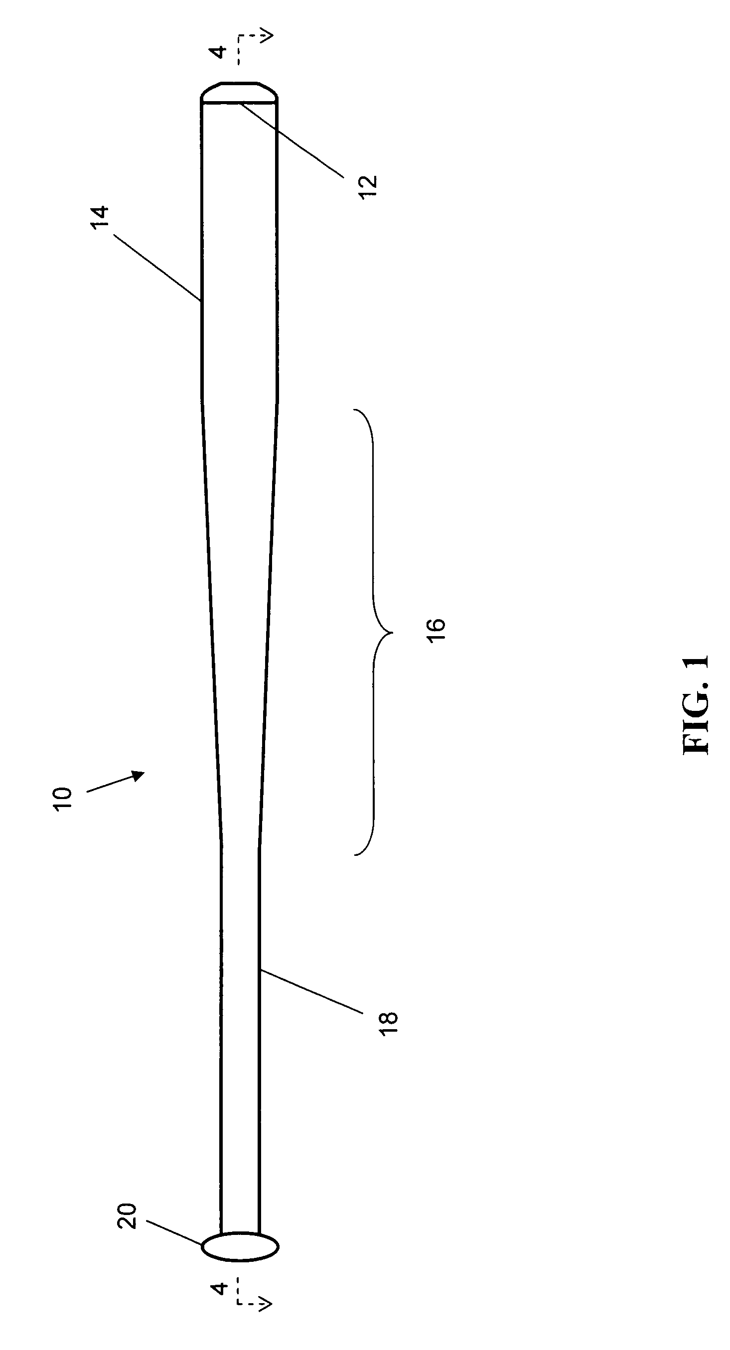
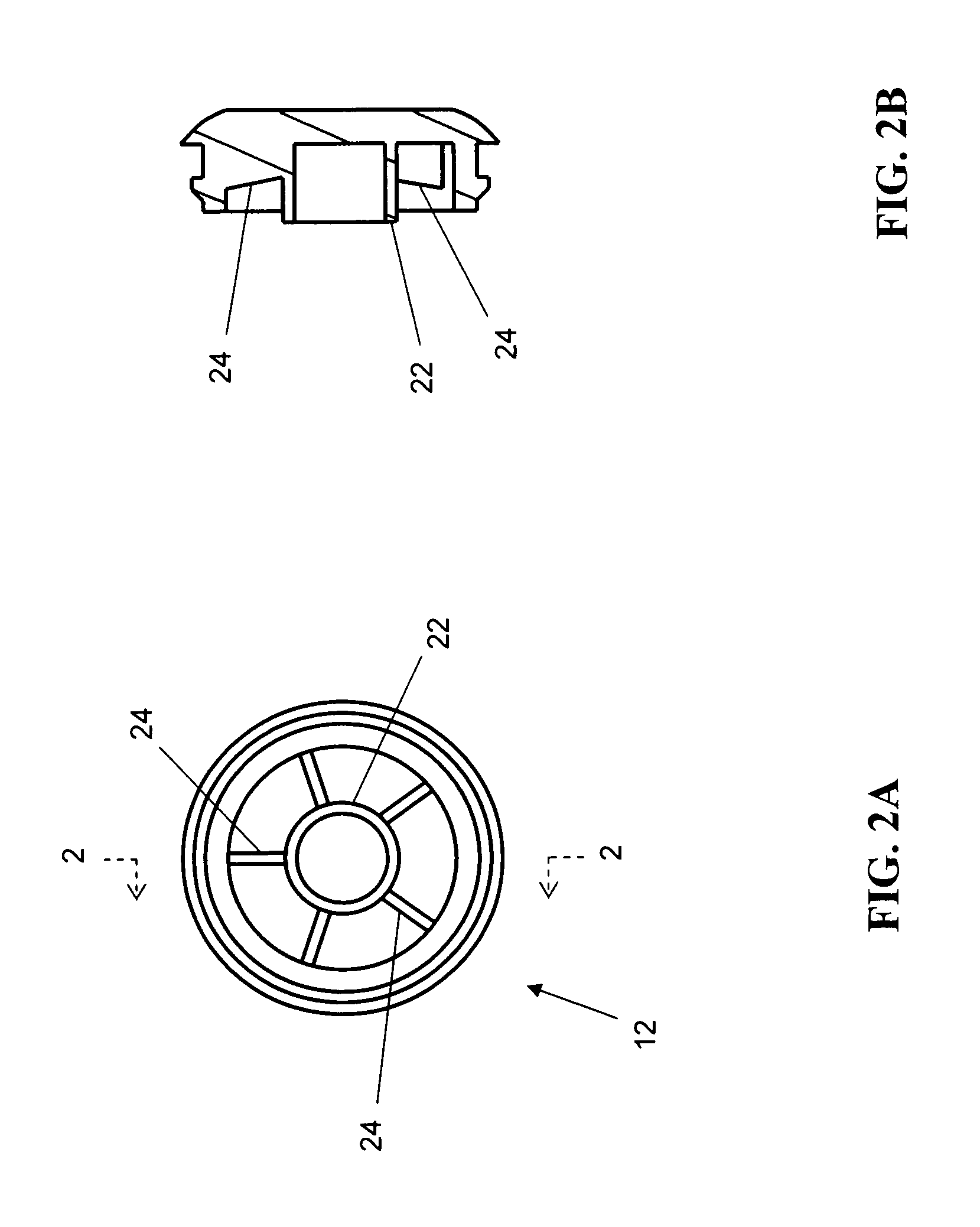
[0047]FIG. 5 depicts the ball bat 110 of the present invention wherein the at least one restriction member 50 is a single restriction member 130. In this embodiment, the single restriction member 130 has a diameter of about 1.75 inches (4.45 cm) and a length of about 0.11 inches (2.8 mm). The single restriction member 130 is located along the length of the central tube 26 at about the same longitudinal station as the center of the optimal hitting area or “sweet spot” of the ball bat 10, about 6.5 inches (16.5 cm) from the end of the ball bat 10. In this embodiment, the central tube 126 includes a single groove 138 which secures and retains the single restriction member 130. The support 134 is preferably positioned around the central tube 126 on a side of the single restriction member 130 opposite the end cap 12. In this embodiment, the 1.39 inch (3.53 cm) long support 134 will extend past the central tube 26, as shown in FIG. 5. In alternative embodiments, a shorter support 134 may ...

third embodiment

[0048]In the present invention, as shown in FIGS. 7A-B, 8A-B, 9A-B, and 10, a ball bat 210 may include at least one resilient member 252 disposed about at least one of the at least one restriction member 250. As previously discussed, when the ball bat 210 impacts a ball, the barrel 214 transiently deforms until the inner surface of the barrel 214 contacts the at least one restriction member 250. The resilient member 252 increases the effective diameter of the at least one restriction member 250, which provides a smaller void 290 between the at least one restriction member 250 and the inner surface of the barrel 214, which can further limit the performance of the ball bat 210. Use of at least one resilient member 252 has also been found to affect the sound upon impact between a ball and the ball bat 210. In one embodiment, the at least one resilient member 252 is a rubber ring encircling or otherwise disposed about the at least one restriction member 250, as shown in FIGS. 9A-B. In a...


PUM

PropertyMeasurementUnit
inner diameteraaaaaaaaaa
diameteraaaaaaaaaa
lengthaaaaaaaaaa

Abstract

Industry regulatory organizations have created performance restrictions for ball bats. The present invention relates to a ball bat with an internal impact dampening means. More particularly, the present invention relates to a ball bat with a handle, a barrel, and a central tube positioned coaxially within the barrel. The central tube includes at least one restriction member capable of limiting the deformation experienced by the ball bat upon impact of a ball. Precisely limiting the deformation of the ball bat allows the present invention to achieve, but not exceed, performance substantially equal to the maximum performance allowed by industry regulatory organizations and maintain that level of performance over a substantial length of the ball bat.

Description

[0001]This application claims the benefit of U.S. Provisional Patent Application Ser. No. 61 / 284,659, entitled BALL BAT WITH INTERNAL DAMPENING MEANS, filed Dec. 22, 2009 to George W. Burger and incorporated herein by reference.BACKGROUND OF THE INVENTION[0002](a) Field of the Invention[0003]Industry regulatory organizations have created performance restrictions for ball bats. The present invention relates to a ball bat with an internal impact dampening means. More particularly, the present invention relates to a ball bat with a handle, a barrel, and a central tube positioned coaxially within the barrel. The central tube includes at least one restriction member capable of limiting the deformation experienced by the ball bat upon impact of a ball. Precisely limiting the deformation of the ball bat allows the present invention to achieve, but not exceed, performance substantially equal to the maximum performance allowed by industry regulatory organizations and maintain that level of p...

Claims


Application Information

Patent Timeline
Patent Type & Authority Patents(United States)
IPC IPC(8): A63B59/06
CPCA63B59/06A63B59/0092A63B59/50A63B59/56A63B60/54A63B2102/18A63B2102/182Y10T29/49826
Inventor BURGER, GEORGE, W.
Owner WILSON SPORTING GOODS
Learn More