
Syringe having a collapsible plunger rod

a plunger rod and syringe technology, applied in the field of syringes with collapsible plunger rods, can solve the problems of affecting the quality of syringes, so as to achieve the effect of reducing length and width

Active Publication Date: 2014-01-21
BECTON DICKINSON FRANCE
View PDF22 Cites 5 Cited by
  • Summary
  • Abstract
  • Description
  • Claims
  • Application Information

AI Technical Summary

Benefits of technology

[0010]Accordingly, there is a general need for a hypodermic syringe that has a reduced length and width when the syringe barrel is filled with a liquid medication prior to injection.

Problems solved by technology

Packaging of such pre-filled syringes, however, tends to be bulky.
Such packaging creates an elongated package that can be awkward for shipping and storage.
The space within these controlled storage locations is often limited, thus there is a need for a syringe assembly that has a smaller packing footprint, to reduce the storage space required for containing the syringe.
This arrangement increases the length of the packaged syringe assembly, which increases costs associated with packaging the pre-filled syringe and takes up additional storage space.

Method used


Image

  • Syringe having a collapsible plunger rod
  • Syringe having a collapsible plunger rod
  • Syringe having a collapsible plunger rod

Examples


Embodiment Construction

[0040]For purposes of the description hereinafter, spatial orientation terms, if used, shall relate to the referenced embodiment as it is oriented in the accompanying drawing figures or otherwise described in the following detailed description. However, it is to be understood that the embodiments described hereinafter may assume many alternative variations and embodiments. It is also to be understood that the specific devices illustrated in the accompanying drawing figures and described herein are simply exemplary and should not be considered as limiting.

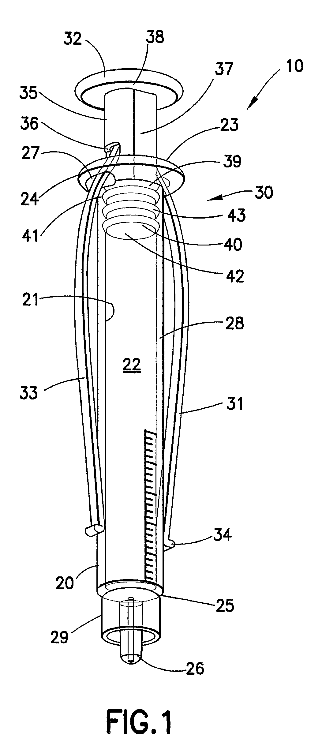
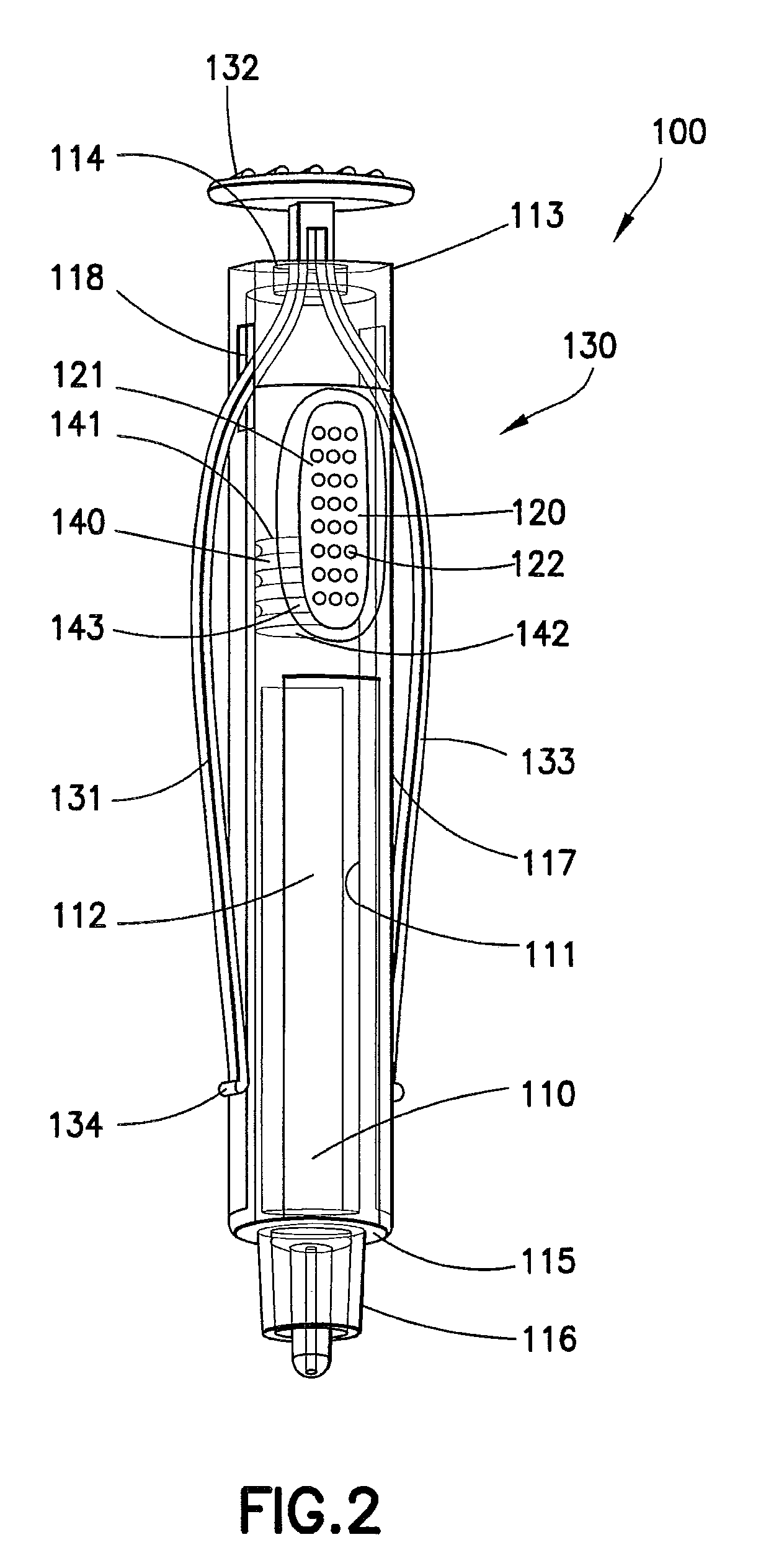
[0041]Referring to FIG. 1, a syringe assembly 10 according to an embodiment of the present invention is shown. The syringe assembly 10 includes a syringe barrel 20 and a plunger assembly 30. As shown in FIG. 1, the syringe barrel 20 has an open proximal end 23 and a distal end 25 opposite to the open proximal end 23. The syringe barrel 20 has an inside surface 21, which defines a chamber 22. As shown, the syringe barrel 20 may have ...


PUM


Abstract

A syringe assembly includes a syringe barrel having an exterior surface, an inside surface defining a chamber, an open proximal end, a distal end, and an outlet disposed adjacent the distal end in fluid communication with the chamber; and a plunger assembly disposed at least partially within the syringe barrel. The plunger assembly includes an elongated plunger rod and a plunger head. The elongated plunger rod is associated with the plunger head to move the plunger head within the chamber of the syringe barrel through an injection cycle. The plunger rod is adapted to move from a collapsed position extending alongside the exterior surface of the syringe barrel to an extended position engaging the plunger head to move the plunger head through the injection cycle.

Description

CROSS REFERENCE TO RELATED APPLICATIONS[0001]This application claims benefit of U.S. Provisional Patent Application Nos. 61 / 235,869 entitled “Syringe Having a Collapsible Plunger Rod” filed Aug. 21, 2009; and 61 / 235,848 entitled “Magnifying Collapsed Plunger Rod” filed Aug. 21, 2009, which are hereby incorporated by reference in their entirety.BACKGROUND OF THE INVENTION[0002]1. Field of the Invention[0003]The present invention relates to a hypodermic syringe that has a compact size, and includes a plunger mechanism positioned externally adjacent the syringe when filled.[0004]2. Description of Related Art[0005]Syringe assemblies, and in particular hypodermic syringes, are well known in the medical field for dispensing fluids, such as medication. A conventional syringe typically includes a syringe barrel with an opening at one end and a plunger mechanism disposed through the other end. The plunger typically includes a plunger rod extending through the barrel, with a plunger head or s...

Claims


Application Information

Patent Timeline
Patent Type & Authority Patents(United States)
IPC IPC(8): A61M5/00A61M31/00A61M5/315
CPCA61M5/31511A61M5/28A61M5/31515A61M2205/583A61M2005/31518A61M5/31565A61M5/3135
Inventor LUM, CHEE LEONGSCHILLER, ERIC
Owner BECTON DICKINSON FRANCE
Learn More