Battery-cell module structure of battery

a battery and module technology, applied in the field of battery module structure of batteries, can solve the problems of increasing weight per one module, limited stacking direction of battery-cell modules, and so as to reduce the burden of assembly workers, facilitate the stacking of layers, and suppress the variation in temperature between battery cells

Inactive Publication Date: 2014-01-21
CALSONIC KANSEI CORP
View PDF16 Cites 6 Cited by
  • Summary
  • Abstract
  • Description
  • Claims
  • Application Information

AI Technical Summary

Benefits of technology

[0007]Therefore, in the present invention, the container main body and the lid part can be easily fixed with each other without using a rolling-up and caulking method, which limits a direction for stacking the battery cell modules, and it can suppress a variation in temperature between the battery cells, decreasing burden on assembly workers.

Problems solved by technology

However, in the conventional battery-cell module structure of the battery, there is a problem in that the direction for stacking layers of the battery-cell modules is limited, because the peripheral end portion of the opening portion of the metal container main body and the peripheral end portion of the end portion of the metal lid are rolled up and caulked with each other so that projecting portions are formed due to rolling-up and caulking on side surfaces of the battery accommodating case.
In addition, there is another problem in that the variation in temperature occurs between battery cells arranged at both end sides and those arranged therebetween, because several sheets of the battery cells are contained in the battery accommodating case and consequently the quantities of heat are different from each other between the battery cells at the both end sides and therebetween.
Further, there is the other problem in that a weight per one module increases and burden on assembly workers becomes larger, because the number of the battery cells is large.

Method used


Image

  • Battery-cell module structure of battery
  • Battery-cell module structure of battery
  • Battery-cell module structure of battery

Examples


first embodiment

[0042]First, a construction of a battery-cell module structure of a battery of a first embodiment will be described.

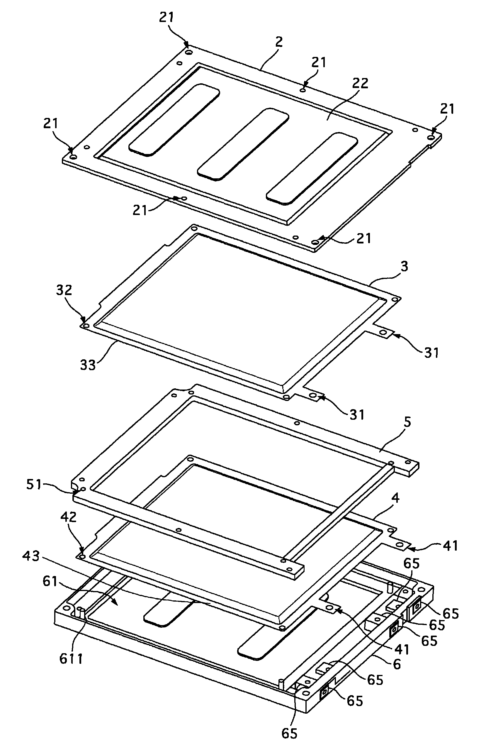
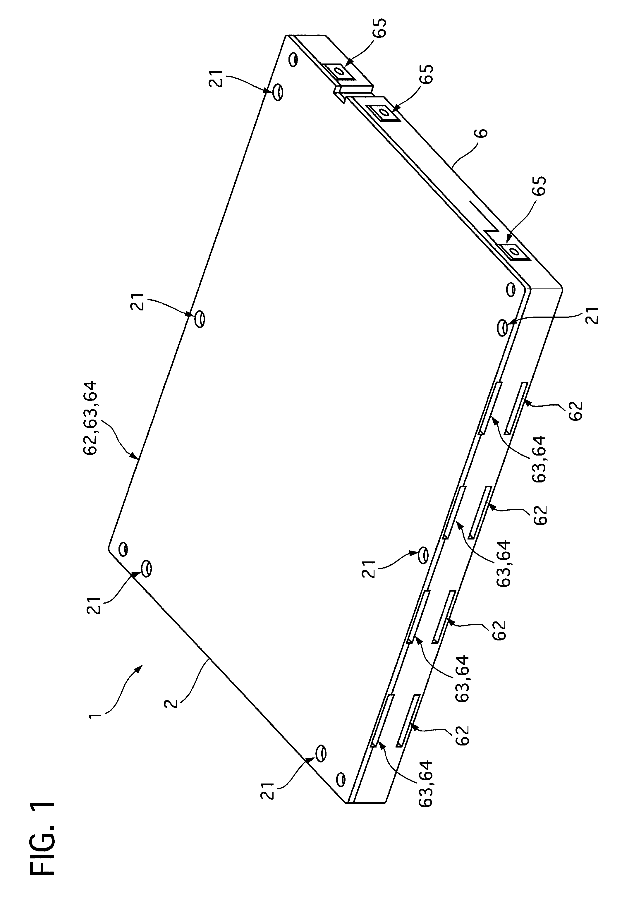
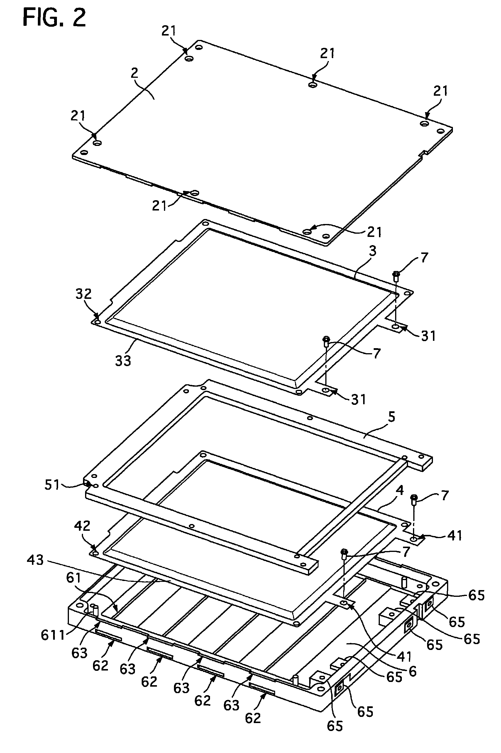
[0043]FIG. 1 is a perspective view showing a battery cell module of the battery of the first embodiment. FIG. 2 is an exploded perspective view showing the battery cell module of the battery of the first embodiment.

[0044]The battery cell module 1 is made of resin, and one module or a plurality of the modules constitute the battery that is mounted on a motor vehicle and the like for example. It is equipped with end terminals for supplying electric power to an exterior (for example, a drive motor of the motor vehicle). The battery cell module 1 of the first embodiment mainly consists of an upper case 2, battery cells 3 and 4, a spacer 5 and a lower case 6.

[0045]The upper case 2 is formed to have a shape like a wide rectangular plate, and it is fixed to the lower case 6 by fastening screws that penetrate through a plurality of attachment holes 21 formed near a peripheral ...

second embodiment

[0085]A second embodiment according to the present invention is an example of a construction where a part of an upper case and a lower case is made of metal, the part being contacted with the battery cells.

[0086]A construction of a battery-cell module structure of a battery of the second embodiment will be described with reference to the accompanying drawings. FIG. 5 is a perspective view showing the battery cell module of the battery of the second embodiment. FIG. 6 is an exploded perspective view showing the battery cell module of the battery of the second embodiment.

[0087]In the battery-cell module structure of the battery of the second embodiment, a portion for screw fastening at one side is made of resin, where the one side is opposite to one edge portion of an upper case 2 corresponding to a side where end terminals 65 of a lower case 6 are provided. The other portion thereof is made of metal to form a metal portion 22. For example, as the upper case 2, a resinous portion fixe...

third embodiment

[0102]A third embodiment according to the present invention is an example where it is constructed so that a part of an upper case and a lower case are made of metal, which is contacted with battery cells.

[0103]A construction of a battery-cell module structure of a battery of the third embodiment will be described with reference to the accompanying drawings.

[0104]FIG. 8 is a perspective view showing a battery cell module of a battery of the third embodiment. FIG. 9 is an exploded perspective view showing the battery cell module of the battery of the third embodiment.

[0105]In the third embodiment, an upper case is made of resin so as to have a shape like a frame, forming a resinous frame portion 23, which includes a portion for screw fastening at a side opposite to one edge of the upper case 2 corresponding to a side where end terminals 65 of a lower case 6 are provided. In addition, an inner side portion of the resinous frame portion 23 is made of metal to form a metal portion 22. Fo...


PUM

PropertyMeasurementUnit
thickaaaaaaaaaa
sizeaaaaaaaaaa
temperatureaaaaaaaaaa

Abstract

A battery-cell structure of a battery is constructed to have a resinous spacer 5 with a frame shape surrounding thick central portions between a battery cell 3 arranged at an upper side and a battery cell 4 arranged at a lower side, and ventilation portions 62 and 64 that are provided in the resinous lower case 6 to communicate the exterior with depressed portions 61 of the resinous lower case 6 and have an up- and down symmetrical shape and size. It is constructed so that the battery cell 3 arranged at the upper side and the battery cell 4 arranged at the lower side are put in a vertical direction between the resinous lower case 6, the spacer 5 and the upper case 2.

Description

TECHNICAL FIELD[0001]The present invention relates to a technology of a battery-cell module structure of a battery.BACKGROUND OF THE INVENTION[0002]A conventional battery-cell module structure of a battery includes a metal container main body and a metal lid to be constructed as a battery accommodating case that has air permeability to communication between an interior and an exterior of the case, where the metal container main body is formed with an opening at-least one side thereof and contains a flat-type assembled battery in which thin batteries are piled up, and the metal lid closes the opening of the metal container main body. A peripheral end portion of an opening end portion of the metal container main body and a peripheral end portion of an end portion of the metal lid are rolled and caulked with each other to construct the battery-cell module structure (For example, refer to Patent Document 1).[0003]Patent Document 1: Japanese Patent Application Laid-Open Publication No. 2...

Claims


Application Information

Patent Timeline
Patent Type & Authority Patents(United States)
IPC IPC(8): H01M6/12H01M2/10H01M10/60H01M10/613H01M10/617H01M10/625H01M10/647H01M10/653H01M10/6554H01M10/6556H01M10/6563H01M50/209
CPCH01M10/0525H01M10/5046H01M10/5032H01M10/5016H01M2/1061Y02E60/12H01M2/1094H01M10/5004H01M10/6551H01M10/647H01M10/625H01M10/613Y02E60/10H01M50/209H01M50/24
Inventor YOSHIHARA, TOSHIKAZUYOSHIOKA, SHINICHI
Owner CALSONIC KANSEI CORP
Why Eureka
Try Eureka