Turbocharging system for internal combustion engine

a technology of internal combustion engine and throttle system, which is applied in the direction of combustion engine, machine/engine, engine controller, etc., can solve the problems of difficult to control the flow in a stable manner and increase the temperature of the compressor side, so as to increase the flow of intake air, the turbocharger is responsive, and the supercharging pressure is increased.

Active Publication Date: 2014-01-28
MITSUBISHI HEAVY IND ENGINE & TURBOCHARGER LTD
View PDF26 Cites 20 Cited by
  • Summary
  • Abstract
  • Description
  • Claims
  • Application Information

AI Technical Summary

Benefits of technology

[0036]In the turbocharging system for the internal combustion engine of the present invention, when the series turbocharging mode is selected, the supercharging pressure is increased and the responsiveness of the turbocharger is enhanced. This is advantageous for the acceleration of the engine. When the parallel turbocharging mode is selected, the flow of the intake air is increased and this is advantageous in the high speed / high load operation. In contrast, in the conventional case using the large size turbocharger and the small size turbocharger, if the parallel mode is selected, an imbalance of the supercharging pressure occurs, thereby requiring adjustment of a check valve, pipes and so on. As a result, the number of parts is increased and the pressure loss is enhanced. However, in the preferred embodiment, none of the issues of the conventional cases is witnessed.
[0037]Further, a high-pressure stage mode and low-pressure stage mode except for the parallel turbocharging mode and the series turbocharging mode can be arbitrarily selected or combined so as to precisely achieve a target engine performance for the intended purpose. And the pipes and the control valves are provided for controlling and thus, the structure can be simplified and is unlikely to cause a system failure.
[0038]Furthermore, two turbochargers that have the same turbine capacity are used. Unlike the conventional case using the combination of the large size turbocharger and the small size turbocharger, two small size turbochargers are used and thus, the system can be downsized and low inertia is obtained.

Problems solved by technology

This generates the issue that the temperature of the compressor side rises and it is necessary to cool the turbochargers or change materials to meet the temperature rise.
As a result, it is difficult to control the flow in a stable manner.

Method used


Image

  • Turbocharging system for internal combustion engine
  • Turbocharging system for internal combustion engine
  • Turbocharging system for internal combustion engine

Examples


Embodiment Construction

[0051]An embodiment of the present invention will now be described in detail with reference to the accompanying drawings. It is intended, however, that unless particularly specified, dimensions, materials, shape, its relative positions and the like shall be interpreted as illustrative only and not limitative of the scope of the present.

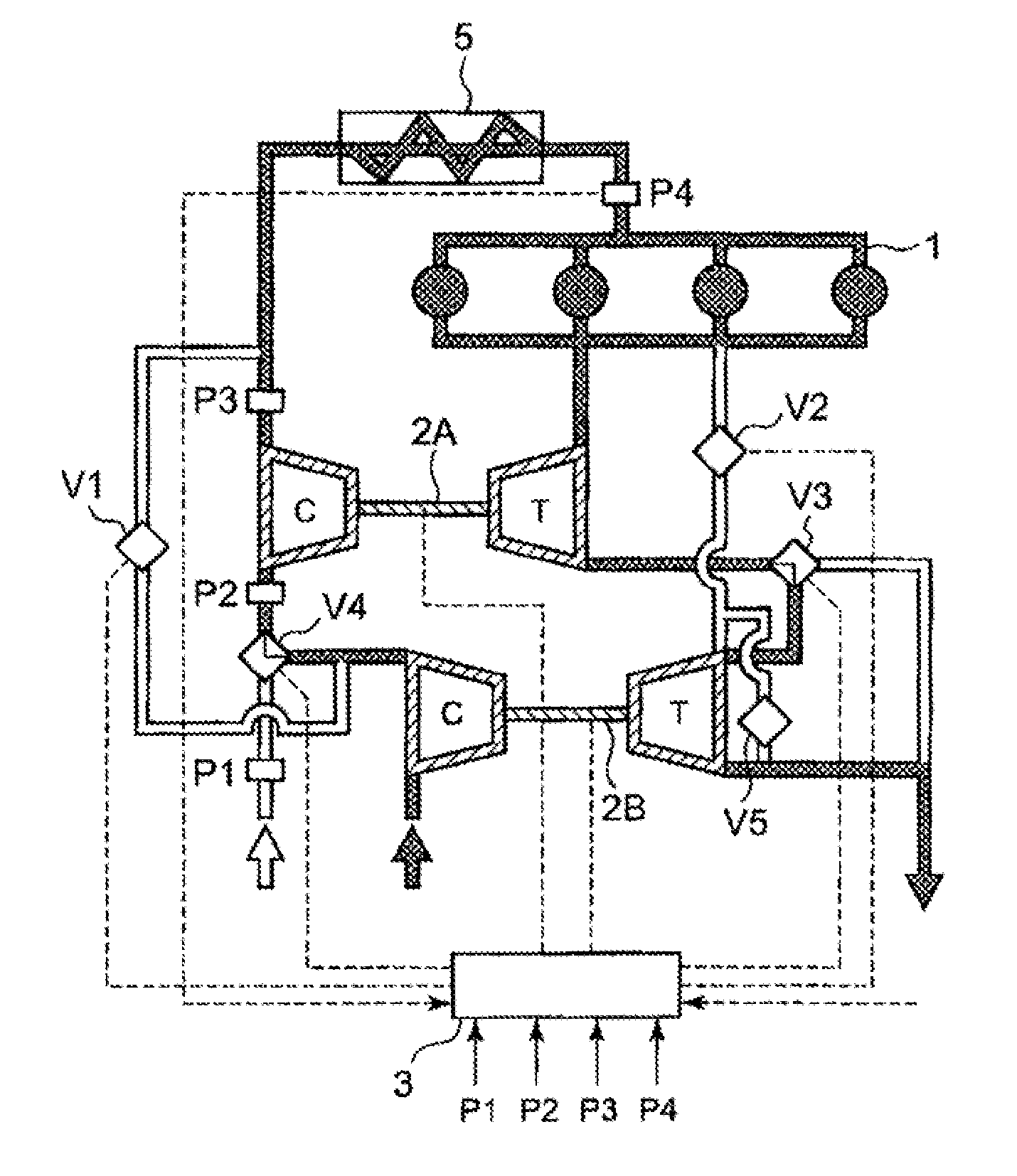
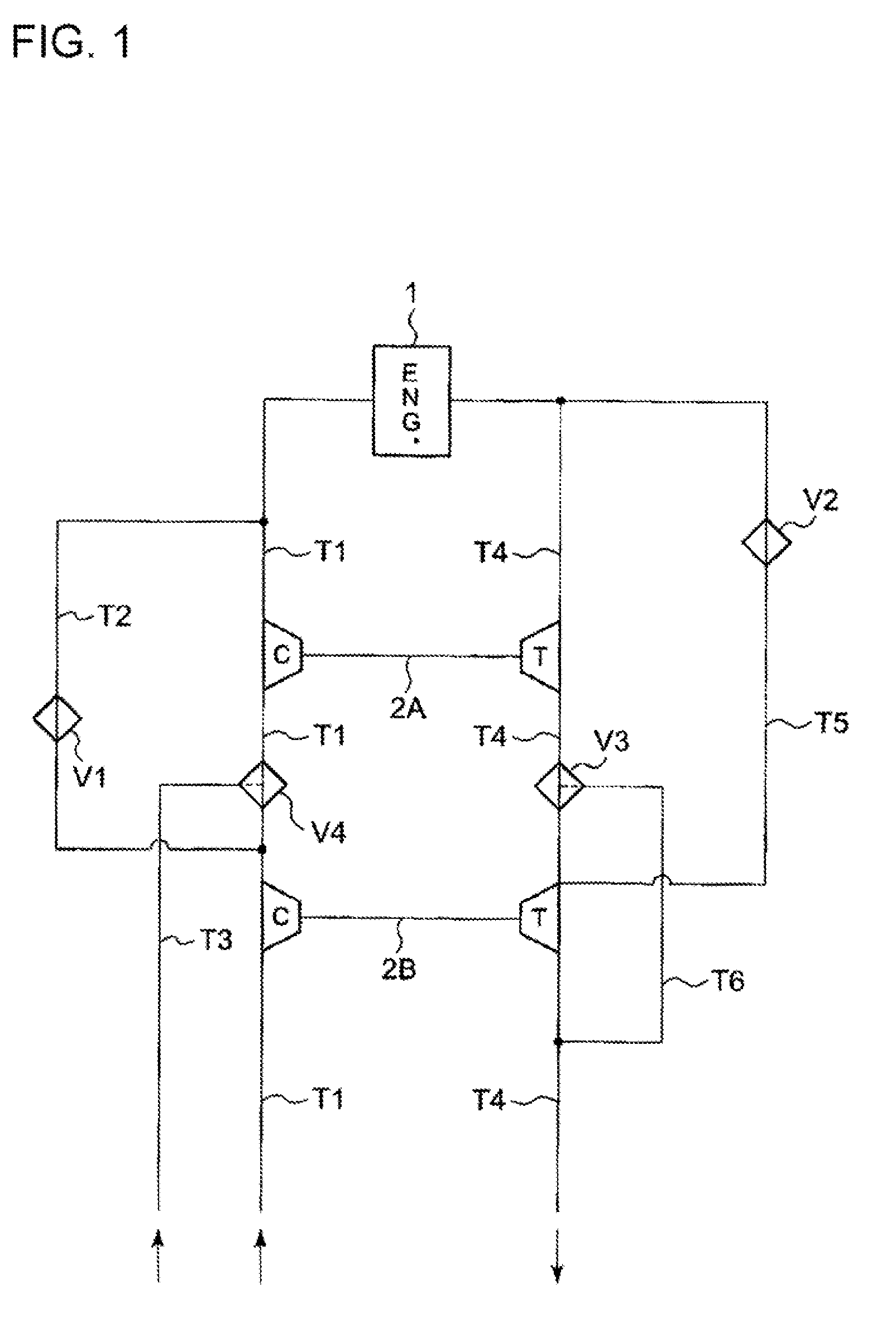
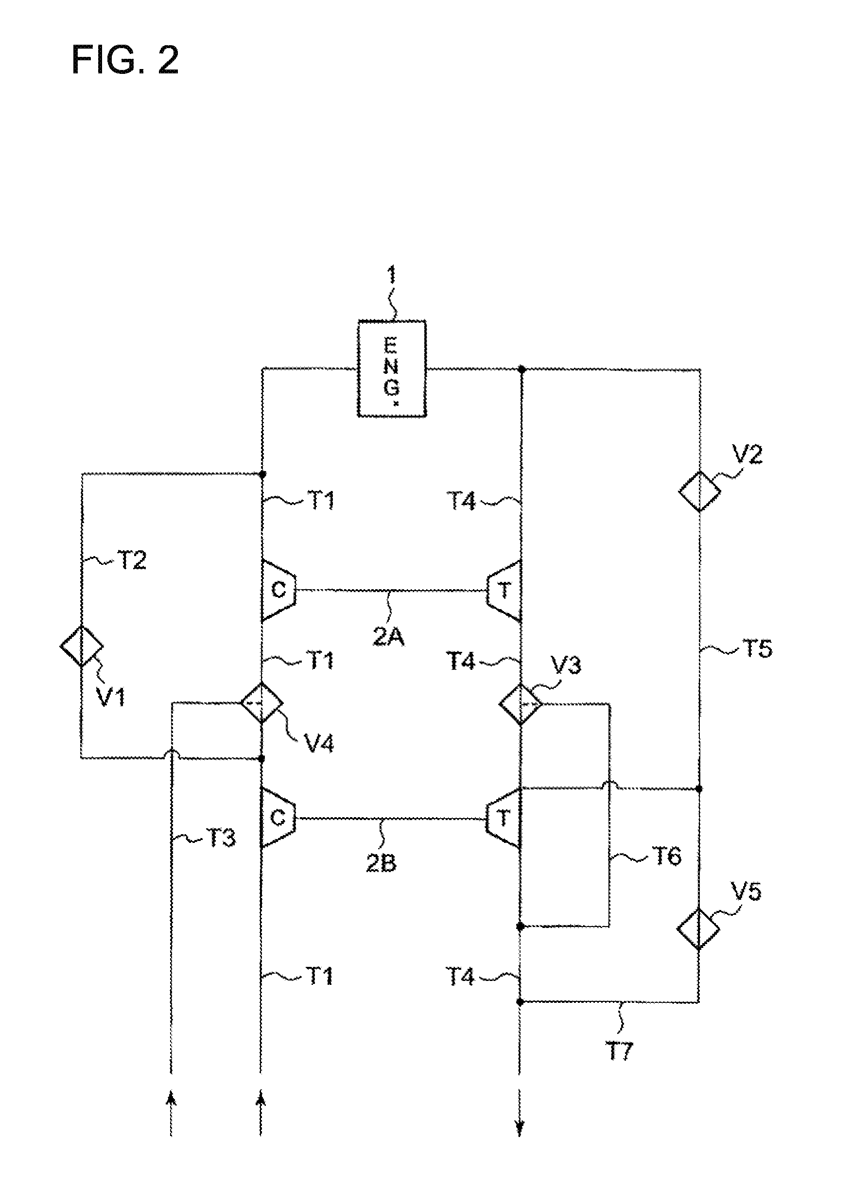
[0052]FIG. 1 is a schematic view illustrating one embodiment of a turbocharging system (two-stage turbocharging system) for an internal combustion engine of the present invention. The turbocharging system of the embodiment comprises an internal combustion engine 1, and a first turbocharger 2A and a second turbocharger 2B which are driven by the exhaust gas from the internal combustion engine 1. The turbocharging system further comprises flow path switching valves V3 and V4 which switch the intake flow path of the intake gas drawn into the internal combustion engine 1 and the exhaust flow path of the exhaust gas from the internal combustion engine 1, a...


PUM


Abstract

A two-stage turbo system provided with an internal combustion engine includes, two turbo-superchargers driven by exhaust gas from the engine, control valves for switching between the flow path of intake gas sucked into the engine and the flow path of exhaust gas, and a control device for controlling the control valves and the turbo-superchargers. The two turbo-superchargers have the same turbine capacity, function respectively as the high-pressure side turbo-supercharger on the exhaust path upstream side and the low-pressure side turbo-supercharger on the exhaust path downstream side, and have, by switching between the flow paths by using the control valves, a series mode in which the two turbo-superchargers are serially connected to each other, a one-stage supercharging mode in which gas flows only to the high-pressure-side turbo-supercharger or only to the low-pressure-side turbo-supercharger, and a parallel mode in which the two turbo-superchargers are connected in parallel to each other.

Description

BACKGROUND OF THE INVENTION[0001]1. Field of the Invention[0002]The present invention relates to a turbocharging system for an internal combustion system equipped with an internal combustion engine and a plurality of turbochargers.[0003]2. Description of the Related Art[0004]As a conventional turbocharging system for an internal combustion engine equipped with an internal combustion engine and a plurality of turbochargers, there is a two-stage turbocharging system having a small size turbocharger on a high-pressure stage, and a large size turbocharger on a low-pressure stage. For instance, Patent Documents 1 and Patent Document 4 disclose a two-stage turbocharging system of this type.[0005]An example structure of the conventional two-stage turbocharging system having the large size turbocharger and the small size turbocharger is explained in reference to FIG. 8 and FIG. 12. FIG. 8 illustrates an example of the conventional two-stage turbocharging system. As shown in the drawing, the...

Claims


Application Information

Patent Timeline
Patent Type & Authority Patents(United States)
IPC IPC(8): F02B37/12
CPCF02B37/007F02B37/013F02B37/004Y02T10/144F02B37/002F02B37/22Y02T10/12F02B37/12
Inventor AN, BYEONGILEBISU, MOTOKI
Owner MITSUBISHI HEAVY IND ENGINE & TURBOCHARGER LTD
Why Eureka
Try Eureka