
Internal structural monitoring system

a monitoring system and structural technology, applied in the direction of structural/machine measurement, force measurement, instruments, etc., can solve the problems of increased maintenance requirements, low cost-benefit ratio, and increased cos

Active Publication Date: 2014-01-28
KCF TECHNOLOGIES
View PDF13 Cites 24 Cited by
  • Summary
  • Abstract
  • Description
  • Claims
  • Application Information

AI Technical Summary

Benefits of technology

The patent is about a system that can monitor the strain and vibration of a structure by placing a sensor inside the structure and using two supports to hold the sensor in place. The sensor is connected to a wireless communication unit, which sends the data to a receiver outside the structure. The wireless communication unit is powered by a power supply inside the structure. The technical effect is that this system can provide safe and accurate monitoring of structures to detect and prevent damage or failure.

Problems solved by technology

Structural monitoring systems have been applied historically in situations where the cost to benefit ratio is low, because the sensor systems add significant cost, additional maintenance requirements, and a level of reliability that may not coincide with that of the structural system being monitored.
For example, health monitoring sensors in power plants are often used because common failures cost millions of dollars in down time, while bridge monitoring sensors are not typically employed because bridges rarely fail and sensor installations are costly.
Wiring faults are common and are often difficult to diagnose, which increases the maintenance required to sustain the monitoring system.
Wire installation costs are high because the wire often needs to be protected.
In addition to wiring, the typical external mounting and means of attachment of a monitoring device to a structure strongly influences their accuracy, performance stability and ultimately lifecycle cost of such devices.
Small degradation in adhesives or mechanical fastener boundary conditions due to corrosion leads to changes in the operation of sensor and power supply, which can radically compromise the value that they offer.
Changes to the sensor mount may require recalibration of device, which erodes the maintenance reduction objectives of the monitoring system.
Changes to the power supply mount can affect output, which compromises the performance of the whole monitoring system.
External mounting of sensor systems presents further drawbacks in terms of vulnerability to external damage or tampering.
In the specific case of helicopter components such as rod ends, replacement is often initiated by the appearance of damage and blemishes in the external surface of the structural part.
These blemishes may result from impacts with small debris during operation or from maintenance activities in the proximity of the structural part.
Considering the robustness of metal components relative to the vulnerability of an externally mounted device of a monitoring system, there is an issue of whether the devices of the monitoring system must be replaced more often than the structure that is being monitored.
A common problem with prior load sensors such as wire foil strain gauges is induced noise from external electromagnetic sources.
This is a particularly relevant issue in structural monitoring systems, if wireless communication and wireless power transfer is used.

Method used


Image

  • Internal structural monitoring system
  • Internal structural monitoring system
  • Internal structural monitoring system

Examples


Embodiment Construction

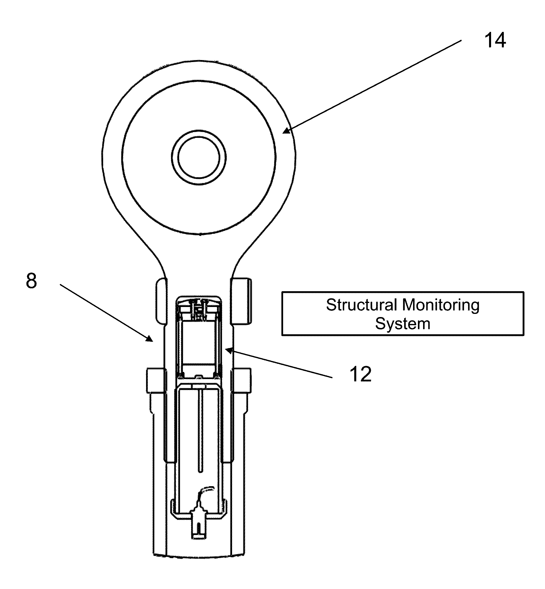
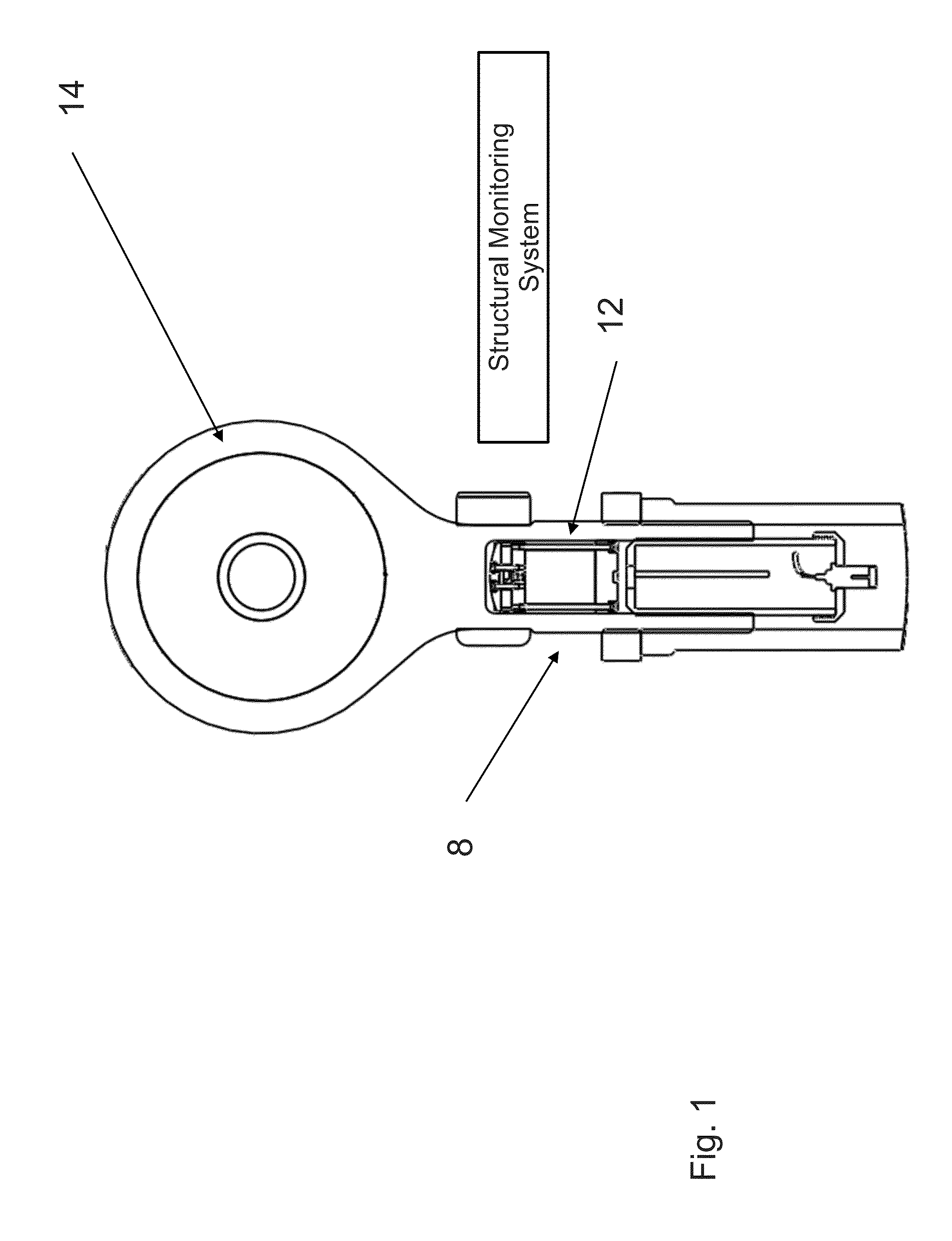
[0022]The present invention is an internal structural monitoring system 8 for a structure as shown in FIG. 1. The present invention includes apparatus and methods associated with the internal structural monitoring system. The present invention includes structure modification and methods of how to modify a structure to receive the internal structural monitoring system. The present invention includes devices as part of the internal structural monitoring system, how to install the devices of internal structural monitoring system within a structure and how to use devices of the internal structural monitoring system within a structure. It further includes features to enable autonomous functionality without the use of wired connectivity to a central processing unit.

[0023]The present invention provides an autonomous internal monitoring system that interrogates a structure or conditions to which the structure is subject. The present invention provides for measuring parameters which characte...


PUM

PropertyMeasurementUnit
diameteraaaaaaaaaa
diameteraaaaaaaaaa
diameteraaaaaaaaaa

Abstract

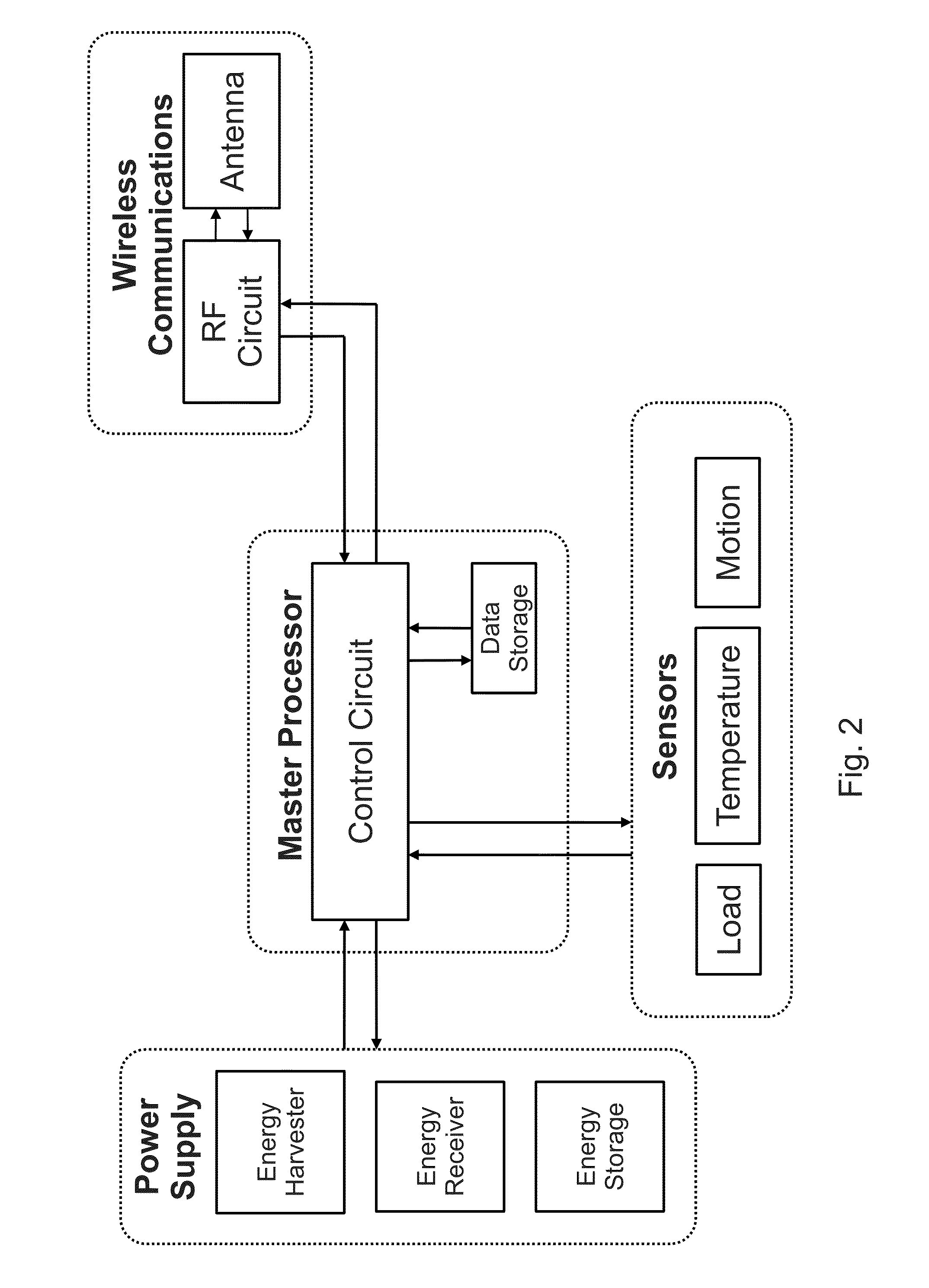
An internal structural monitoring system for a structure that includes a sensor mounted within the structure to measure at least one of strain experienced by the structure and vibration experience by the structure. It includes a first system support mounted and second system support mounted in the structure, where the first system and the second system support are mounted in the structure such that the sensor is between the first system support and the second system support to hold the sensor in position so that the sensor senses at least one of strain and vibration. It includes a wireless communication unit mounted within the structure, the wireless communication unit connected to the sensor to receive data from the sensor and transmit the data to a receiver outside the structure. It includes a power supply mounted within the structure to supply necessary electrical power to the sensor and the communication unit.

Description

[0001]This application claims the benefit of and incorporates by reference U.S. Provisional Application No. 61 / 361,723 filed Jul. 6, 2010.[0002]This invention was made with United States government support under U.S. Navy SBIR Award No. N68335-09-C-0176. The government has certain rights in this invention.BACKGROUND OF THE INVENTION[0003]The present invention relates generally to structural monitoring systems, and more particularly to monitoring systems embedded within a structure that includes autonomous power supplies, sensors, and wireless communication.[0004]Structural monitoring is a known field used to examine the integrity of structures and predict when maintenance activities should be performed. Most conventional prior art in this field pertains to sensor systems which use sensors that are wired to a central data acquisition and processing unit. Structural monitoring systems have been applied historically in situations where the cost to benefit ratio is low, because the sens...

Claims


Application Information

Patent Timeline
Patent Type & Authority Patents(United States)
IPC IPC(8): G01L1/00
CPCG01L1/125G01L5/0004G01M5/00G01M5/0041G01L1/00G01L1/26G01M5/0066
Inventor LOVERICH, JACOBWENNER, STEPHEN J.FRANK, JEREMY E.
Owner KCF TECHNOLOGIES
Learn More