Optical fiber structure monitoring and analysis

a technology of optical fiber and structure, applied in the direction of optical elements, optical apparatus testing, instruments, etc., can solve the problems of reducing the structural integrity of those structures, the factor of safety cannot prevent the gradual erosion of structural integrity, and the measurement is limited to specific points or elements, so as to achieve better vibration transmission

Active Publication Date: 2012-03-27
AT&T INTPROP I LP
View PDF14 Cites 11 Cited by
  • Summary
  • Abstract
  • Description
  • Claims
  • Application Information

AI Technical Summary

Benefits of technology

[0006]The monitoring fibers can be coupled to the monitored structure using a gel for better transmission of vibrations. If the optical fiber is routed through a conduit, the gel can be used to fill the conduit. Alternatively, if the fiber is acoustically coupled to the exterior of the structural element, a U-channel can be used to hold the fiber in place and filled with the gel to acoustically couple the fiber to the structure.

Problems solved by technology

As buildings, bridges and other structures age, the structural integrity of those structures begins to decline.
However, a factor of safety can not prevent the gradual erosion of structural integrity that occurs over time or the impact of man-made accidents or natural disasters.
However, these measurements are limited to the specific points or elements measured and do not provide a broad and detailed view of the integrity of the entirety of the structure.

Method used


Image

  • Optical fiber structure monitoring and analysis
  • Optical fiber structure monitoring and analysis
  • Optical fiber structure monitoring and analysis

Examples


Embodiment Construction

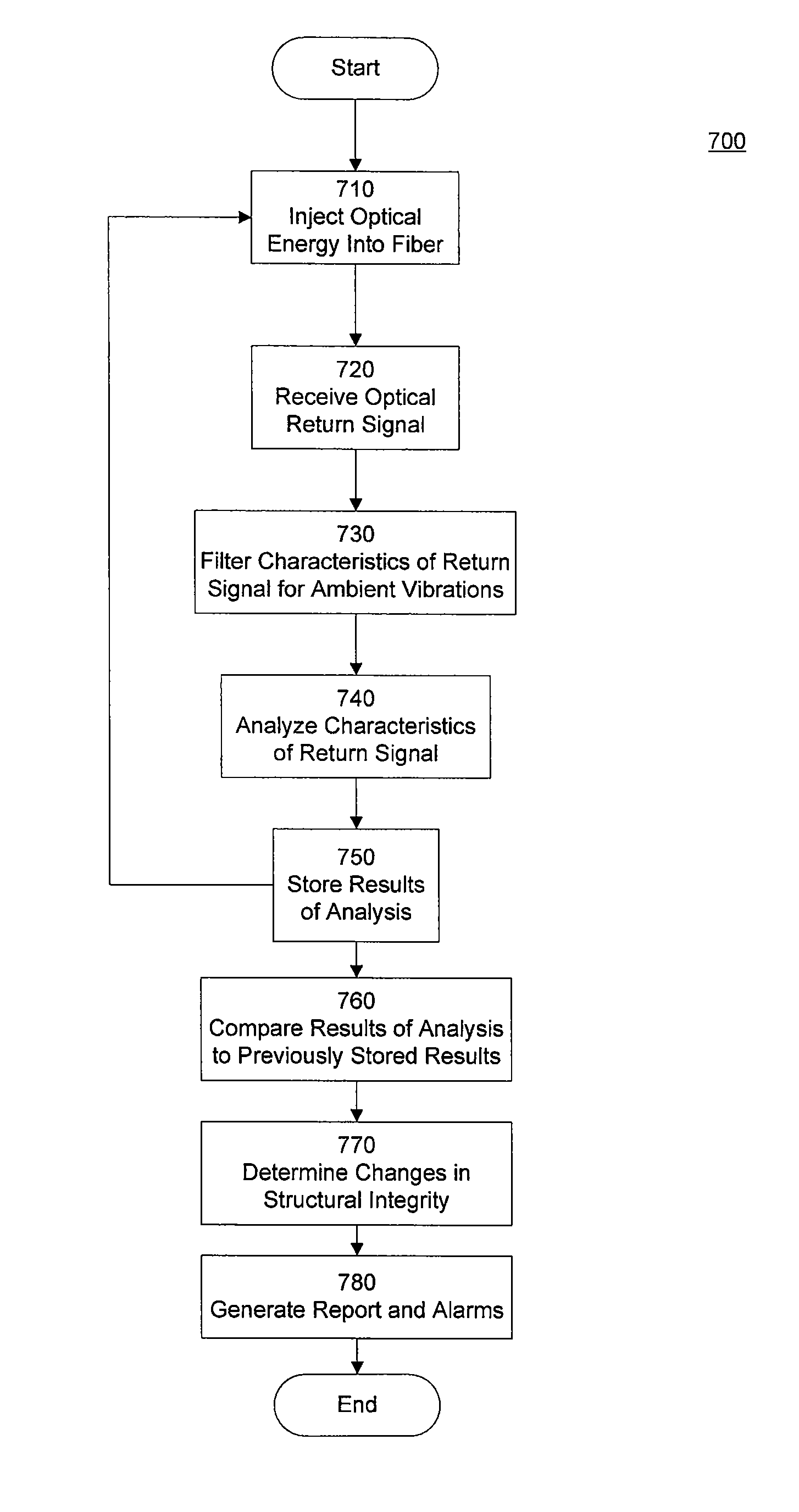
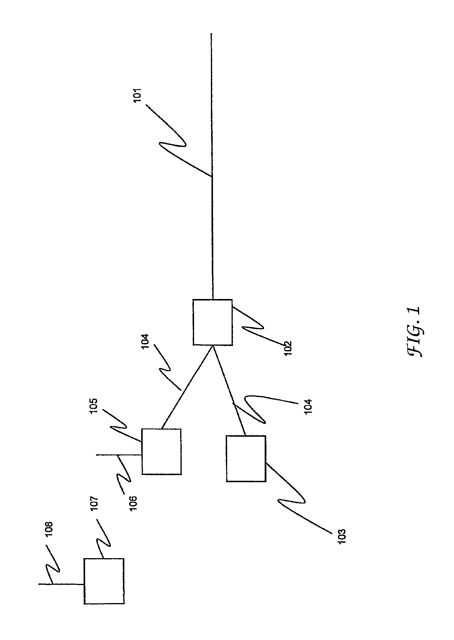
[0020]FIG. 1 is a schematic representation of a remote fiber surveillance configuration in accordance with one embodiment of the present disclosure. In this Figure, optical energy source 103 injects optical energy into fiber 101. As would be understood by persons having ordinary skill in the art, the source 103 of optical energy can be, for example, a laser. Detector 105 detects the return signal (i.e., the “backscattered signal”) emitted from the fiber in accordance with the particular technology used by the surveillance system, such as Raleigh scattering or OTDR technology. As would be understood by persons having ordinary skill in the art, the detector 105 of optical energy can be, for example, a semiconductor photo-detector. Detector 105 can also include the necessary electronics (e.g., an analyzer), such as a digital signal processor, for analyzing the return signal to determine, for example, characteristics of an exemplary acoustic signal impinging upon the fiber at some point...


PUM


Abstract

A system and method for monitoring the structural integrity of a structure is provided. An optical fiber is acoustically coupled to one or more of the structural elements. A source of optical energy is configured to inject optical energy into the optical fiber, and an optical detector is configured to detect a first optical return signal having characteristics that are affected by vibrations of the structural elements. An analyzer measures characteristics of the optical return signal to determine information concerning the movement of the structural elements monitored by the fiber optic cable. The results of the analyzer can be stored and so that the analysis of the optical return signal can be compared to previously recorded signals to determine changes in structural integrity over time. Multiple fibers can be acoustically coupled to the monitored structural elements to obtain additional data concerning the structural integrity.

Description

FIELD OF THE DISCLOSURE[0001]The present disclosure relates to optical fiber surveillance systems and methods, and more particularly to methods and systems for monitoring structures and structural integrity using optical fiber surveillance systems.BACKGROUND[0002]As buildings, bridges and other structures age, the structural integrity of those structures begins to decline. To ensure such structures to not fail, engineers and architects incorporate a factor of safety into designs. However, a factor of safety can not prevent the gradual erosion of structural integrity that occurs over time or the impact of man-made accidents or natural disasters. Structural integrity can be monitored by measuring the deformation of movement of buildings over time. Similarly, strain and stress gages can be applied to or built into buildings. However, these measurements are limited to the specific points or elements measured and do not provide a broad and detailed view of the integrity of the entirety o...

Claims


Application Information

Patent Timeline
Patent Type & Authority Patents(United States)
IPC IPC(8): G01B9/02
CPCG01M5/00G01M11/083
Inventor HUFFMAN, JOHN SINCLAIR
Owner AT&T INTPROP I LP
Why Eureka
Try Eureka