Structural monitoring of wind turbine with fibre bragg grating sensors in each blade

a technology of fibre optic sensors and wind turbines, applied in the direction of propellers, propulsive elements, water-acting propulsive elements, etc., can solve the problems of significantly complicating the selection of blades for balancing turbines, affecting the maintenance of appropriate inventory, and affecting the selection of turbine blades

Active Publication Date: 2010-08-19
MOOG INSENSYS
View PDF8 Cites 11 Cited by
  • Summary
  • Abstract
  • Description
  • Claims
  • Application Information

AI Technical Summary

Benefits of technology

[0016]In a preferred configuration, the multiplexer comprises a signal path from each optical fibre to the optical output that is different in length to the signal path from the other optical fibres, such that signals from a given optical fibr

Problems solved by technology

This imposes limitations on the selection of turbine blades in that the blade must be selected both to have the appropriate weight for a balanced turbine and the appropriate wavelength of sensors to prevent ambiguity in the sensor

Method used


Image

  • Structural monitoring of wind turbine with fibre bragg grating sensors in each blade
  • Structural monitoring of wind turbine with fibre bragg grating sensors in each blade
  • Structural monitoring of wind turbine with fibre bragg grating sensors in each blade

Examples


Embodiment Construction

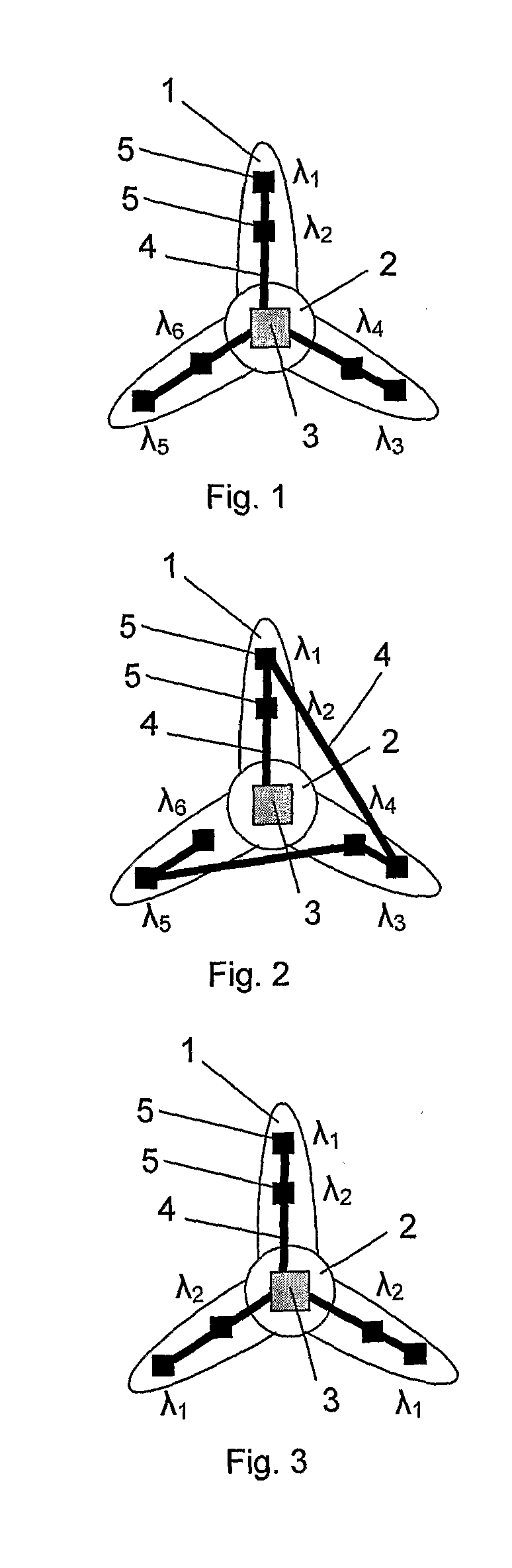
[0032]FIG. 1 is a schematic view of a wind turbine incorporating optical fibre strain sensors for structural monitoring. The turbine comprises three blades 1 connected to a hub 2. Located within the hub 2 is a data processing device (instrument) 3 which sends and receives pulses of light to and from optical fibre strain sensors 5 mounted to each of the blades 1. The optical fibre strain sensors 5 are connected to the instrument 3 by optical fibres 4. When the blades 1 flex in the wind, the resonant wavelength of the Bragg gratings forming the strain sensors 5 changes and from this change in resonant wavelength, the strain on the blade 1 can be determined.

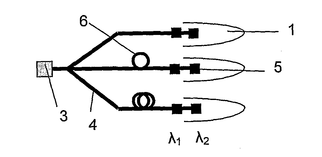
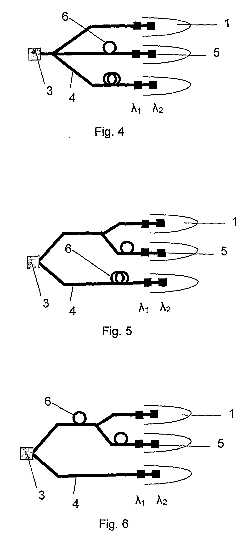
[0033]A typical optical fibre sensor system uses wavelength division multiplexing (WDM) to accommodate the signals from each strain sensor 5 along the optical fibre 4. Each sensor in the same array is identified by its wavelength λ and must therefore have a different wavelength at all times from other sensors 5 in the same array. Tw...


PUM

PropertyMeasurementUnit
Lengthaaaaaaaaaa
Wavelengthaaaaaaaaaa

Abstract

A system for the structural monitoring of blades 1 on a wind turbine. Each blade 1 has respective optical fibre bragg grating sensors 5. The system has a number of input connectors, which connect to the strain sensors 5 of respective blades 1. A single output connector connects to a data processing device 3 which processes signals from the strain sensors 5. The input connectors each have a signal path to the output connector that is different in length to the signal path from the other input connectors, such that signals from a given blade 1 can be identified at the data processing device 3 by the time of arrival of the signals. The system has the advantage that the each of the blades 1, including the sensors attached to it or embedded within it can be identical and therefore interchangeable.

Description

FIELD OF THE INVENTION[0001]This invention relates to the structural monitoring of wind turbine blades and, in particular, to the structural monitoring of wind turbine blades using fibre optic sensors. The invention extends to a method of manufacturing a wind turbine.BACKGROUND TO THE INVENTION[0002]Blades for wind turbines are typically constructed of glass-reinforced plastics (GRP) on a sub-structure, which may be formed of wood, glass fibre, carbon fibre, foam or other materials. Graphite fibre in epoxy resin is also used. The plastics resin can be injected into a mould containing the sub-structure to form the outer surface of the blade. The blade may also be built up as a series of layers of fibre material and resin. In some cases, the fibre material is pre-impregnated with resin.[0003]A typical wind turbine blade may have a length of between 20 and 60 metres or more. As the interior of the blade is generally hollow, a “floor” is provided within the blade proximate the hub-engag...

Claims


Application Information

Patent Timeline
IPC IPC(8): F03D11/00B23P15/04G01L1/24G01D5/353
CPCF03D11/0091F05B2270/808G01D5/35303G01L1/246Y10T29/49336G01M5/0041G01M5/0091G01M11/083Y02E10/722G01M5/0016F03D17/00G01D5/35316G01D5/35354G01B11/165G01D5/35383
Inventor VOLANTHEN, MARKRHEAD, PHILIP MARKJONES, MARTIN PETER WILLIAMLLOYD, GLYNN DAVID
Owner MOOG INSENSYS
Why Eureka
Try Eureka