Imaging device
a technology of a display panel and an image, applied in the field of imaging devices, can solve the problems of difficult to compute a precise correction amount, difficult to compute the correction amount, and errors in determining the deterioration, so as to improve the image quality of the display panel using organic el elements, reduce the cost of operation, and prolong the life
- Summary
- Abstract
- Description
- Claims
- Application Information
AI Technical Summary
Benefits of technology
Problems solved by technology
Method used
Image
Examples
first embodiment
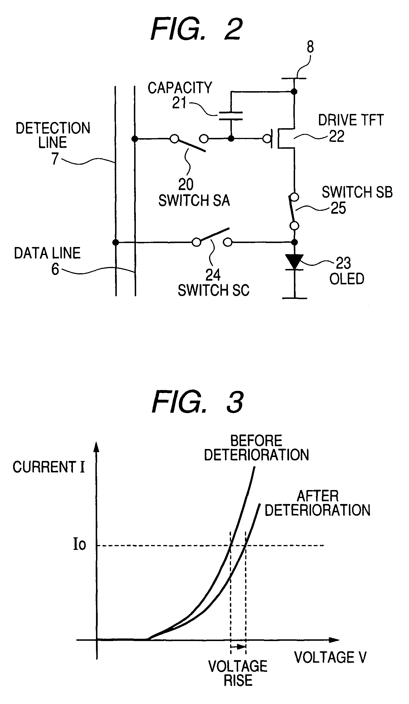
[0040]The prior art embodiment shows a method for detecting a pixel property where it was not necessary to consider the effect of temperature dependence, initial property, etc. of the pixels 5 in the display area. Hereafter, an embodiment will be described where the effect of temperature dependence is taken into consideration. FIG. 7 is a plan view showing a display panel identical to that of FIG. 5 describing the problem when temperature dependence is taken into consideration. FIG. 8 is a voltage-current characteristic diagram illustrative of the temperature dependence of an organic EL element. FIG. 9 is a waveform diagram identical to that of FIG. 6 that changes due to temperature dependence of the organic EL element. When the display panel using the organic EL element is illuminated, the panel temperature rises. In particular, since the temperature rise in the center (high-temperature part) of the display panel 2 is sharp, and there is a low temperature part 33 on the edge of the...
second embodiment
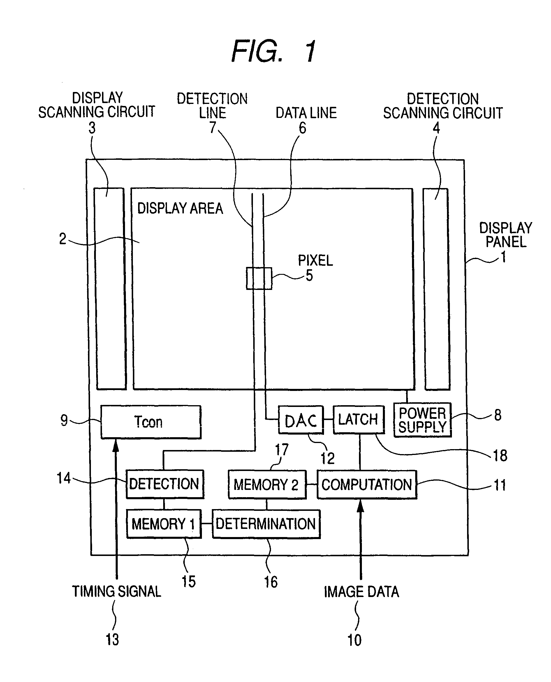
[0048]FIG. 15 is a diagram of essential components describing an imaging device having a function for detecting and determining pixel burnout according to a second embodiment of the invention. According to this embodiment, plural pixels 5 in areas 57 shaded in FIG. 15 are taken as one of the blocks 57, and burnout detection and determination are performed in this block unit. First, the scanning lines G1 to Gm of the area 57 are selected sequentially by the detection scanning circuit 4, and switches the S1 to Si are selected sequentially while one scanning line is selected. To do this, all of the pixels 5 in the block 57 are selected sequentially.
[0049]A fixed current is passed through the selected pixels 5 from the current source. A voltage generated in the organic EL due to this fixed current is input to the buffer amplifier 56, and input to the analog / digital converter ADC at a low impedance. The analog / digital converter ADC converts this voltage to digital data, and stores it in ...
third embodiment
[0052]FIG. 16 is a diagram of essential components showing an imaging device having a function for detecting and determining pixel burnout according to a third embodiment of the invention. In this embodiment, the block 57 is formed by two adjacent pixels 5 in the scanning line direction shown by a1, a2, a3, a4, . . . , and burnout is determined by comparing with the adjacent pixel. The detection and determination procedure is as follows. First, one scanning line, here the scanning line G1, is selected by the detection scanning circuit 4. While this scanning line G1 is selected, the switches S1 to Sj are switched ON one after another, a fixed current is passed from the current source 54, and the corresponding voltage is stored in the first memory 15 via the buffer amplifier 56 and ADC. After the characteristics of all the organic EL elements of the pixels 5 in one scanning line have been detected, the determination circuit 16 performs a comparison with adjacent pixels for the voltage...
PUM
| Property | Measurement | Unit |
|---|---|---|
| temperature | aaaaa | aaaaa |
| voltage | aaaaa | aaaaa |
| brightness | aaaaa | aaaaa |
Abstract
Description
Claims
Application Information
 - R&D
- Intellectual Property
- Life Sciences
- Materials
- Tech Scout
- Unparalleled Data Quality
- Higher Quality Content
- 60% Fewer Hallucinations
Browse by: Latest US Patents, China's latest patents, Technical Efficacy Thesaurus, Application Domain, Technology Topic, Popular Technical Reports.
© 2025 PatSnap. All rights reserved.Legal|Privacy policy|Modern Slavery Act Transparency Statement|Sitemap|About US| Contact US: help@patsnap.com


