Method of compensating for clipping in input scanners

a scanner and input technology, applied in the field of document scanner calibration systems and methods, can solve the problems of reducing the dynamic range, the number of actual brightness levels available, and the contribution of clipped pixels to erroneous patch averages, so as to facilitate the improvement of error estimation for scanner calibration. or printer

Inactive Publication Date: 2010-11-18
XEROX CORP
View PDF3 Cites 3 Cited by
  • Summary
  • Abstract
  • Description
  • Claims
  • Application Information

AI Technical Summary

Benefits of technology

[0008]In accordance with various aspects described herein, systems and methods are described that facilitate improving error estimation for calibration of a scanner or printer. For example, a method of calibrating a scanner or printer comprises measuring pixel values, for one or more calibration patches comprising a plurality of pixels, at each of a first predetermined maximum pixel value and a second predetermined maximum pixel value. The method further comprises computing a first average pixel value from scan data acquired at the first predetermined maximum pixel value and identifying a first set of omitted pixels, and computing a second average pixel value from scan data acquired at the second predetermined maximum pixel value and identifying a second set of omitted pixels. The method additionally comprises identifying calibration patches that do not have pixels omitted when measured at the first predetermined maximum pixel value, but that have pixels omitted when measured at the second predetermined maximum pixel value. Moreover, the method comprises generating a linear model from the identified calibration patches, wherein the linear model is used to predict patch averages based on the pixels having pixel values below the second predetermined maximum pixel value and a number of omitted pixels from each of a plurality of color separations. The method further comprises employing the linear model to determine an error between the first and second average pixel values, and calibrating the scanner while compensating for the determined error.

Problems solved by technology

However, when a scanner is used as a surrogate for a spectrophotometer, for example, clipped pixels contribute to erroneous patch averages.
Yet another approach involves using a scanner with less gain, and therefore less (or no) chance of clipping any pixels, which has the undesirable effect of reducing dynamic range, and hence the number of actual brightness levels available.
It is difficult to reduce noise without increasing the cost of the scanner, other than by increasing the number of pixels averaged.
The error resulting from clipping generally increases as the number of pixels clipped increases, rising slowly until the number approaches 50% of the pixels.
However the principle still holds: as the number of pixels clipped increases, the error in the mean increases exponentially, and even for relatively small numbers of clipped pixels, it increases.

Method used


Image

  • Method of compensating for clipping in input scanners
  • Method of compensating for clipping in input scanners
  • Method of compensating for clipping in input scanners

Examples


Embodiment Construction

[0015]In accordance with various features described herein, systems and methods are described that overcome the above-described problems by increasing the accuracy of a calibration method, both at the very light and the very dark end of the brightness spectrum. The systems and methods described herein are applied to images containing calibration patches, such as are used for printer calibration.

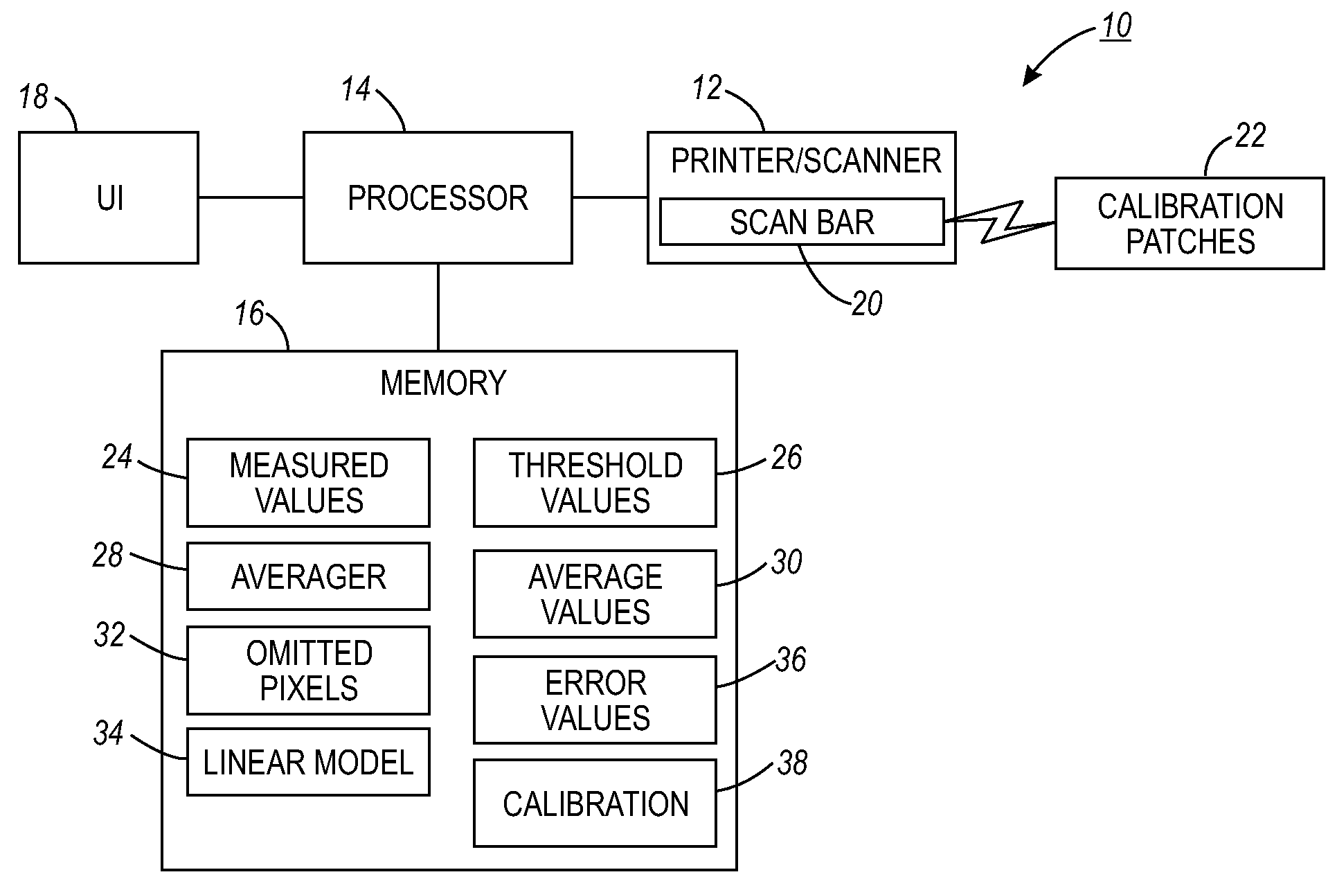
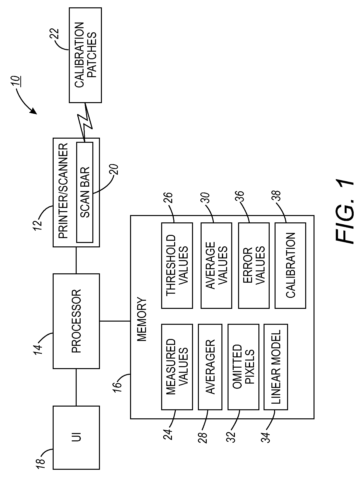
[0016]With reference to FIG. 1, a calibration system 10 includes a printing device 12, such as a printer or scanner, which is coupled to a processor 14. The processor 14 is additionally coupled to a memory 16, and optionally to a user interface 18 by which information is presented to and / or received from a user. The printing device 12 includes a scan bar 20 that scans one or more calibration patches or sheets 22 to measure pixel values thereon for calibrating the printer 12. For example, a Xerox Freeflow™ 655 full-width array scan bar can be used to scan the calibration patches 22 for use in ...


PUM


Abstract

Systems and methods are described that facilitate improving error estimation for calibration error due to clipping of pixels, and compensation therefor, during calibration of a scanner or printer. Calibration patches are measured at a first maximum pixel value threshold and at a slightly lower threshold value. Pixel values for the patches at each threshold are averaged, and a linear model is constructed, which is employed to predict error due to pixel clipping. The error is then compensated for when calibrating the scanner or printer.

Description

BACKGROUND[0001]The subject application relates to document scanner calibration systems and methods. While the systems and methods described herein relate to document scanners and the like, it will be appreciated that the described techniques may find application in other scanning systems, other xerographic applications, and / or other calibration methods.[0002]Document scanners generally produce a fixed number of bits (e.g., 8) per separation, forcing their values to be within a specific range. One design parameter that affects scanner calibration is the level to which the “white” value of a calibration strip translates when the calibration is applied. Using classical approaches, values brighter than the white calibration value are clipped. A very small amount of clipping is desirable in most applications, since for all but the very few pixels clipped, the image has a higher dynamic range. However, when a scanner is used as a surrogate for a spectrophotometer, for example, clipped pi...

Claims


Application Information

Patent Timeline
Patent Type & Authority Applications(United States)
IPC IPC(8): H04N1/00H04N1/04
CPCH04N1/00002H04N1/00013H04N1/00015H04N1/00031H04N1/00045H04N1/4076H04N1/00063H04N1/00068H04N1/00087H04N1/0009H04N1/00053
Inventor KLASSEN, R. VICTOR
Owner XEROX CORP
Why Eureka
Try Eureka