Grinding robot and method for grinding electrically conductive workpieces

Pending Publication Date: 2019-11-14
VOITH PATENT GMBH
View PDF0 Cites 0 Cited by
  • Summary
  • Abstract
  • Description
  • Claims
  • Application Information

AI Technical Summary

Benefits of technology

[0006]The present invention provides a grinding robot for grinding electrically conductive workpieces wherein the control of the grinding process in normal operation occurs exclusively by measuring electrical values.
[0007]The present invention also provides a grinding robot for grinding an electrically conducting workpiece including a grinding wheel. The grinding wheel includes an undulated tool receptacle which defines an axis of rotation about which the grinding wheel can rotate during grinding, a head which is rotationally symmetrical with respect to the axis of rotation, and the head contains abrasive material and has a grinding surface that is configured for contacting the workpiece during grinding, a measuring and transmission unit, and at least one conductor strand pair including two conductor strands which are electrically insulated from one another. The conductor strands are embedded in the head and extend from the grinding surface of the head into an interior of the head and are electrically connected with the measuring and transmission unit. The grinding robot further includes an actuation device for actuating the grinding wheel, and a control system which is connected with the actuation device and which controls the grinding wheel. The conductor strands are arranged in such a way that during grinding, due to the contact with the workpiece, a closed electrical circuit is created for measuring a resistance value, wherein the electric circuit progresses from the measuring and transmission unit via one conductor strand, the workpiece, and the other conductor strand back to the measuring and transmission unit, and the conductor strands are designed in such a way that a measured resistance is dominated by a resistance of conductor strands, so that the measured resistance is a reciprocal proportional measurement for a degree of wear of the head. The measuring and transmission unit is configured for measuring and transmitting the measured resistance to the control system and wherein the control system is configured for considering the measured resistance in determining whether a predefined surface contour of the workpiece has been achieved.
[0008]The present invention also provides a method for grinding an electrically conducting workpiece. The method includes an initial step of providing a grinding robot for grinding the electrically conducting workpiece. The grinding robot includes a grinding wheel, the grinding wheel includes an undulated tool receptacle which defines an axis of rotation about which the grinding wheel can rotate during grinding, a head which is rotationally symmetrical with respect to the axis of rotation, and the head contains abrasive material and has a grinding surface that is configured for contacting the workpiece during grinding, a measuring and transmission unit, and at least one conductor strand pair including two conductor strands which are electrically insulated from one another. T

Problems solved by technology

For the narrow tolerances of the aforementioned hydrau

Method used


Image

  • Grinding robot and method for grinding electrically conductive workpieces
  • Grinding robot and method for grinding electrically conductive workpieces
  • Grinding robot and method for grinding electrically conductive workpieces

Examples


first embodiment

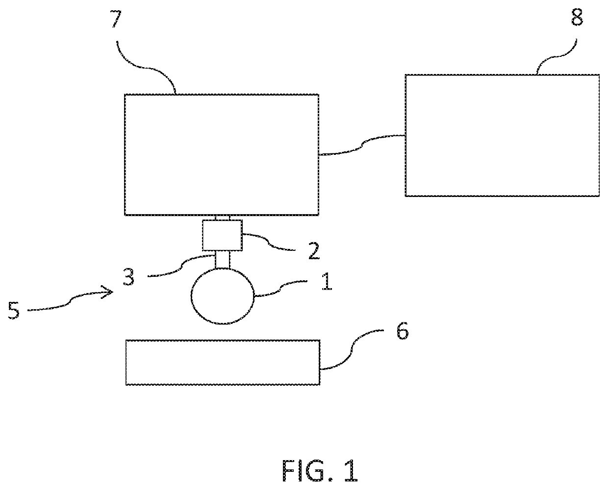
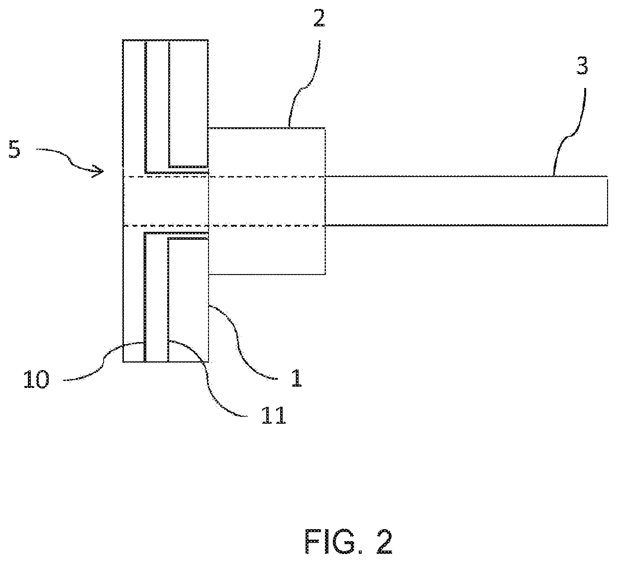
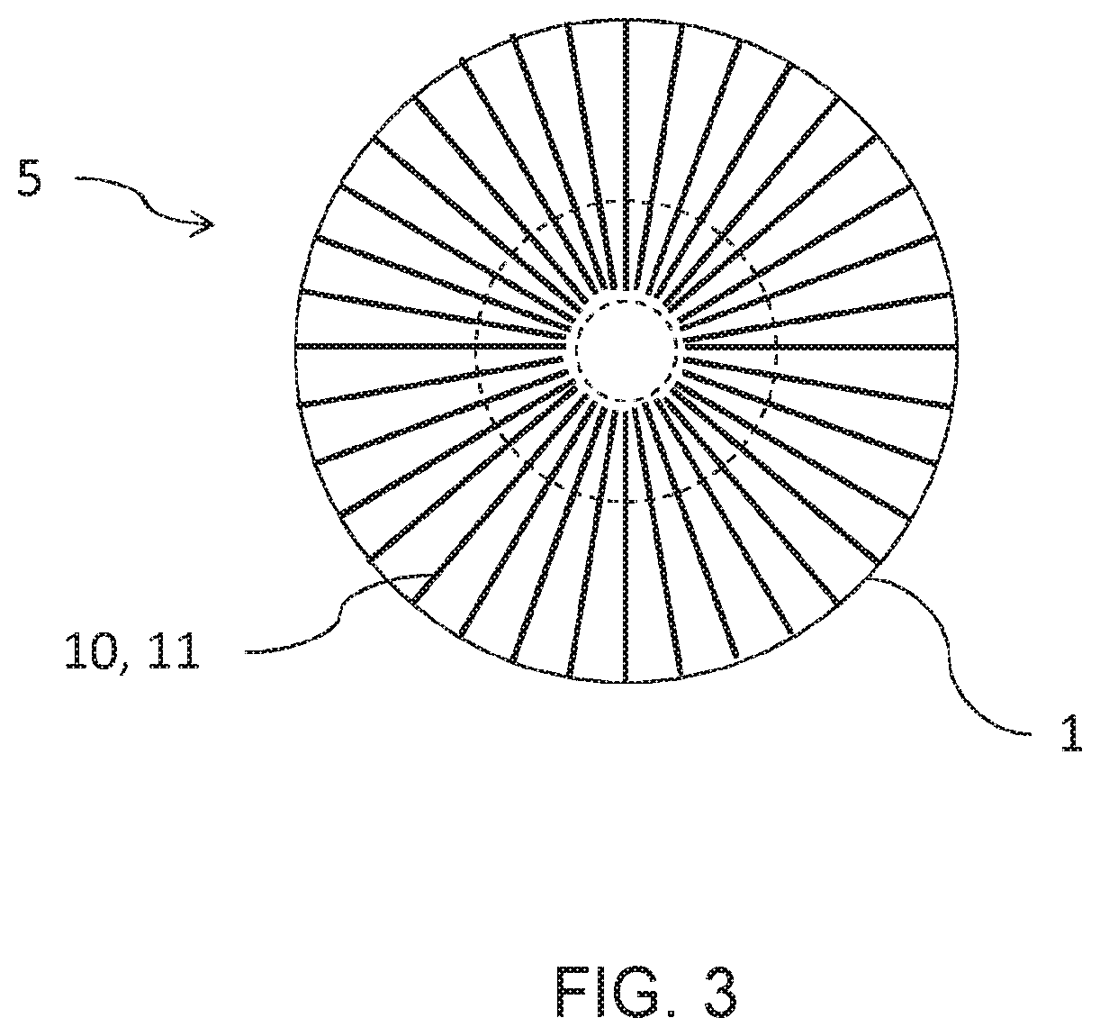
[0018]FIG. 2 illustrates a grinding wheel 5 for use in an inventive grinding robot in a first embodiment, along the axis of rotation. During operation, the grinding wheel 5 rotates around tool receptacle 3. Grinding wheel 5 also includes a measuring and transmission unit 2. The measuring and transmission unit 2 is equipped with an independent power supply, which can be for example a battery or a super capacitor (not illustrated). At least two conductor strands 10 and 11 are embedded into the rotationally symmetrical head 1. The conductor strands 10 and 11 extend in each case from the outer surface of rotationally symmetrical head 1 which is in contact with workpiece 6 during operation, to the interior of head 1 where they are electrically connected with measuring and transmission unit 2. The conductor strands 10 and 11 are electrically insulated from one another, which is achieved either by a separation of the conductor strands 10, 11 from one another or through electrical insulatio...

second embodiment

[0023]FIG. 4 illustrates a sectional view along the rotational axis of a grinding wheel 5 for use in an inventive grinding robot. The same identification references are used as in FIGS. 1-3. Grinding wheel 5 illustrated in FIG. 4 has a rotationally symmetric head 1 which has a spherical shape. Since such a head 1 makes rather selective contact with the workpiece, conductor strand pairs 10, 11 must run much closer adjacent to one another onto the surface of head 1 and must progress closely together in the expected region of wear of head 1. Thus, conductor strand pairs 10, 11 are shown in each case in FIG. 4 only as a single line. It is clear that as a rule, this arrangement necessitates that conductor strands 10 are electrically insulated from conductor strands 11. One option for achieving this is in the use of coaxial cables which are insulated from one another, that is to say, one of conductor strands 10 or 11 surrounds the other one in a tubular manner, wherein a suitable insulati...


PUM


Abstract

A grinding robot for grinding an electrically conducting workpiece. The grinding robot includes a grinding wheel, an actuation device for actuating grinding wheel, and a control system. The grinding wheel including an undulated tool receptacle which defines an axis of rotation about which the grinding wheel can rotate during grinding, and a head which is rotationally symmetrical with respect to the axis of rotation, and which contains abrasive material and has a grinding surface which is in contact with workpiece during grinding. The grinding wheel also includes a measuring and transmission unit and at least one conductor strand pair with two conductor strands which are electrically insulated from one another. The conductor strands are embedded in the rotationally symmetrical head and extend from the grinding surface of the head into the interior of the head and are electrically connected with measuring and transmission unit.

Description

CROSS REFERENCE TO RELATED APPLICATIONS[0001]This is a continuation of PCT application No. PCT / EP2017 / 081302, entitled “GRINDING ROBOT FOR GRINDING ELECTRICALLY CONDUCTIVE WORKPIECES, AND METHOD FOR OPERATING SAME”, filed Dec. 4, 2017, which is incorporated herein by reference.BACKGROUND OF THE INVENTION1. Field of the Invention[0002]The present invention relates to a grinding robot for grinding electrically conductive workpieces, and a method for operating a grinding robot.2. Description of the Related Art[0003]Grinding robots are known from the current state of the art. The approach of the grinding wheel toward the workpiece is controlled by measuring of the position of the grinding wheel in the direction toward the workpiece, and by measuring the force which is being exerted by the workpiece upon the grinding wheel. EP 0 421 323 A1 discloses a grinding wheel which is controlled by measuring the force exerted by the workpiece upon the grinding wheel.[0004]Measurement of the specif...

Claims


Application Information

Patent Timeline
IPC IPC(8): B24B49/10B24B41/04B24D5/00
CPCB24B41/04B24B49/10B24D5/00B24B19/14B24B27/0038B24B49/183B24D3/346B24B41/002B24B1/002
Inventor ROHRER, MARTINWEIGL, FLORIANKARNER, STEFAN
Owner VOITH PATENT GMBH
Why Eureka
Try Eureka