
Detection and correction of impulse noise in communication channel crosstalk estimates

a technology of crosstalk estimation and detection and correction, applied in the field of communication systems, can solve problems such as affecting the throughput and affecting the performance of the system

Active Publication Date: 2017-05-30
RPX CORP
View PDF10 Cites 1 Cited by
  • Summary
  • Abstract
  • Description
  • Claims
  • Application Information

AI Technical Summary

Benefits of technology

This approach provides substantial immunity to impulse noise, enhancing the accuracy of crosstalk estimates and maintaining system performance even in the presence of impulse noise, with simulation results showing a significant reduction in estimation error.

Problems solved by technology

Multi-channel communication systems are often susceptible to interference between the various channels, also referred to as crosstalk or inter-channel crosstalk.
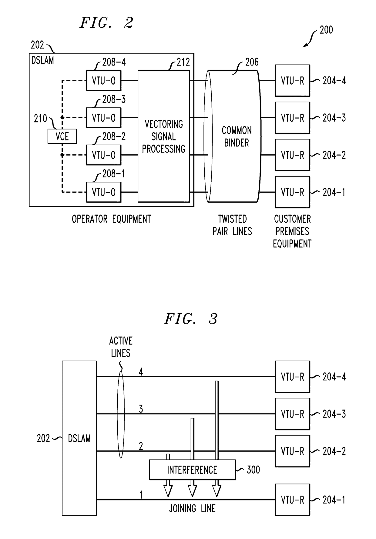
One of the major impairments in such systems is crosstalk between multiple subscriber lines within the same binder or across binders.
Thus, signals transmitted over one subscriber line may be coupled into other subscriber lines, leading to interference that can degrade the throughput performance of the system.
More generally, a given “victim” channel may experience crosstalk from multiple “disturber” channels, again leading to undesirable interference.
In conventional DSL systems, it can be difficult to generate sufficiently accurate crosstalk estimates in the presence of impulse noise.
Nonetheless, impulse noise remains a significant problem in pilot signal aided estimation of crosstalk.
For example, even a single impulse occurring during crosstalk estimation can degrade the estimates so severely that there is a significant SNR loss caused when the estimates are used for vectoring.
Crosstalk estimates based on error feedback techniques are particularly vulnerable to such impulse noise.
If even a single sync symbol is corrupted by impulse noise, the resulting crosstalk estimates may be extremely poor.

Method used


Image

  • Detection and correction of impulse noise in communication channel crosstalk estimates
  • Detection and correction of impulse noise in communication channel crosstalk estimates
  • Detection and correction of impulse noise in communication channel crosstalk estimates

Examples


Embodiment Construction

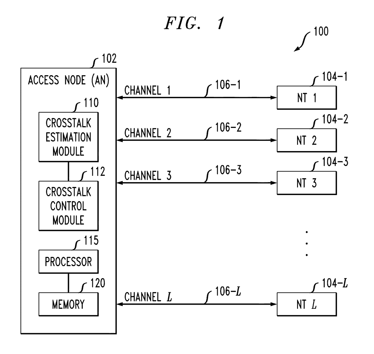
[0018]The present invention will be illustrated herein in conjunction with exemplary communication systems and associated techniques for crosstalk control in such systems. The crosstalk control may be applied substantially continuously, or in conjunction with activating of subscriber lines or other communication channels in such systems, tracking changes in crosstalk over time, or in other line management applications. It should be understood, however, that the invention is not limited to use with the particular types of communication systems and crosstalk control applications disclosed. The invention can be implemented in a wide variety of other communication systems, and in numerous alternative crosstalk control applications. For example, although illustrated in the context of DSL systems based on DMT modulation, the disclosed techniques can be adapted in a straightforward manner to a variety of other types of wired or wireless communication systems, including cellular systems, mu...


PUM


Abstract

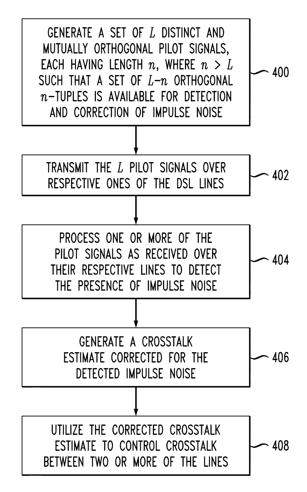
An access node of a communication system is configured to control crosstalk between channels of the system. A set of L distinct and linearly independent pilot signals is generated, with each pilot signal having length n, where n>L such that n−L linearly independent n-tuples are available for use in detection and correction of impulse noise. In an illustrative embodiment, the L pilot signals are mutually orthogonal. The L pilot signals are transmitted over respective ones of the channels, and one or more of the pilot signals as received over their respective channels are processed to detect the presence of impulse noise. A crosstalk estimate corrected for the detected impulse noise is generated and utilized to control crosstalk between two or more of the channels.

Description

FIELD OF THE INVENTION[0001]The present invention relates generally to communication systems, and more particularly to techniques for mitigating, suppressing or otherwise controlling interference between communication channels in such systems.BACKGROUND OF THE INVENTION[0002]Multi-channel communication systems are often susceptible to interference between the various channels, also referred to as crosstalk or inter-channel crosstalk. For example, digital subscriber line (DSL) broadband access systems typically employ discrete multi-tone (DMT) modulation over twisted-pair copper wires. One of the major impairments in such systems is crosstalk between multiple subscriber lines within the same binder or across binders. Thus, signals transmitted over one subscriber line may be coupled into other subscriber lines, leading to interference that can degrade the throughput performance of the system. More generally, a given “victim” channel may experience crosstalk from multiple “disturber” c...

Claims


Application Information

Patent Timeline
Patent Type & Authority Patents(United States)
IPC IPC(8): H04B1/38H04L5/16H04L25/02H04B3/487
CPCH04L25/0228H04B3/487H04L25/02
Inventor ASHIKHMIN, ALEXEI E.WHITING, PHILIP ALFRED
Owner RPX CORP
Learn More