Eureka AIR delivers breakthrough ideas for toughest innovation challenges, trusted by R&D personnel around the world.

Carrier with adjustable parallel track structure for retaining musical instruments

a parallel track, adjustable technology, applied in the direction of instruments, transportation and packaging, music aids, etc., can solve the problems of limiting or altering the natural walking or rapid stride movement of users, carriers have limitations, and cannot provide the combination of features disclosed and claimed

Active Publication Date: 2014-02-11
RANDALL MAY INT
View PDF42 Cites 11 Cited by
  • Summary
  • Abstract
  • Description
  • Claims
  • Application Information

AI Technical Summary

Benefits of technology

[0010]It is an object of the shoulder mounted apparatus is to provide a carrier that allows a user to carry and play one or more drums while they transport the drum such as when they are walking, marching or rapidly moving. The mounting allows for the drum(s) to be maintained in a horizontal or rotated vertical orientation where the drumheads are oriented in a horizontal configuration allowing the drum to be played by striking the drumhead(s).
[0011]It is another object of the drum mounting apparatus, when it is configured with a single sliding (mono) post, to provide a simplified mounting apparatus that allows height of the horizontal playing surface of the drum to be raised and lowered by sliding the drum mounting apparatus on the single (mono) post. The mounting apparatus on the carrier has a vertical slot and the mounting apparatus on the drum has a horizontal pin or rod that slides into the vertical slot to secure the drum on the carrier. The drum is quickly removed from the carrier by lifting the pin or rod out of the slot.
[0012]It is another object of the drum mounting apparatus, when it is configured as with two or more posts to provide a stable box structure for the drum(s) to be supported on the carrier. The box structure refers to the two sets of slides or tracks that are mounted to the carrier and a corresponding two sets of slides are mounted on hardware having vertically or horizontally oriented slots or saddle. An array of drums is mounted to a tenor rail that engages onto the vertically or horizontally oriented slots or saddle to support the drums on the carrier. The overhung cantilevered weight of the drums secures the drum array in the vertically or horizontally oriented slots or saddle. The ability to integrate the slides onto the carrier allows the drums to be more rigidly secured to the carrier and significantly reduces flexing of the drum or drum array with the carrier to improve the stability of the playing surface when the user is moving or playing the drums. When the drums are brought closer to the user the overhung distance is decreased and the cantilevered load is decreased and reduces the strain on the back of the user. Since the tenor rail rests in the vertically or horizontally oriented slots or saddle the tenor rail can be slid horizontally in the carrier to justify the drums left or right of the center of the user. A user can place one or more marks on the tenor rail to identify specific balancing or positioning locations for the drum array when drums of different sizes and weights are placed in the drum array.

Problems solved by technology

A number of drum holding apparatus have been patented and used, but none provide the combination of features disclosed and claimed herein.
These carriers have limitations that require an abdominal plate that is an integral part of the carrier.
Because of the mechanical structure of these carriers they restrict or alter natural walking or rapid stride movement of the user.

Method used


Image

  • Carrier with adjustable parallel track structure for retaining musical instruments
  • Carrier with adjustable parallel track structure for retaining musical instruments
  • Carrier with adjustable parallel track structure for retaining musical instruments

Examples


Embodiment Construction

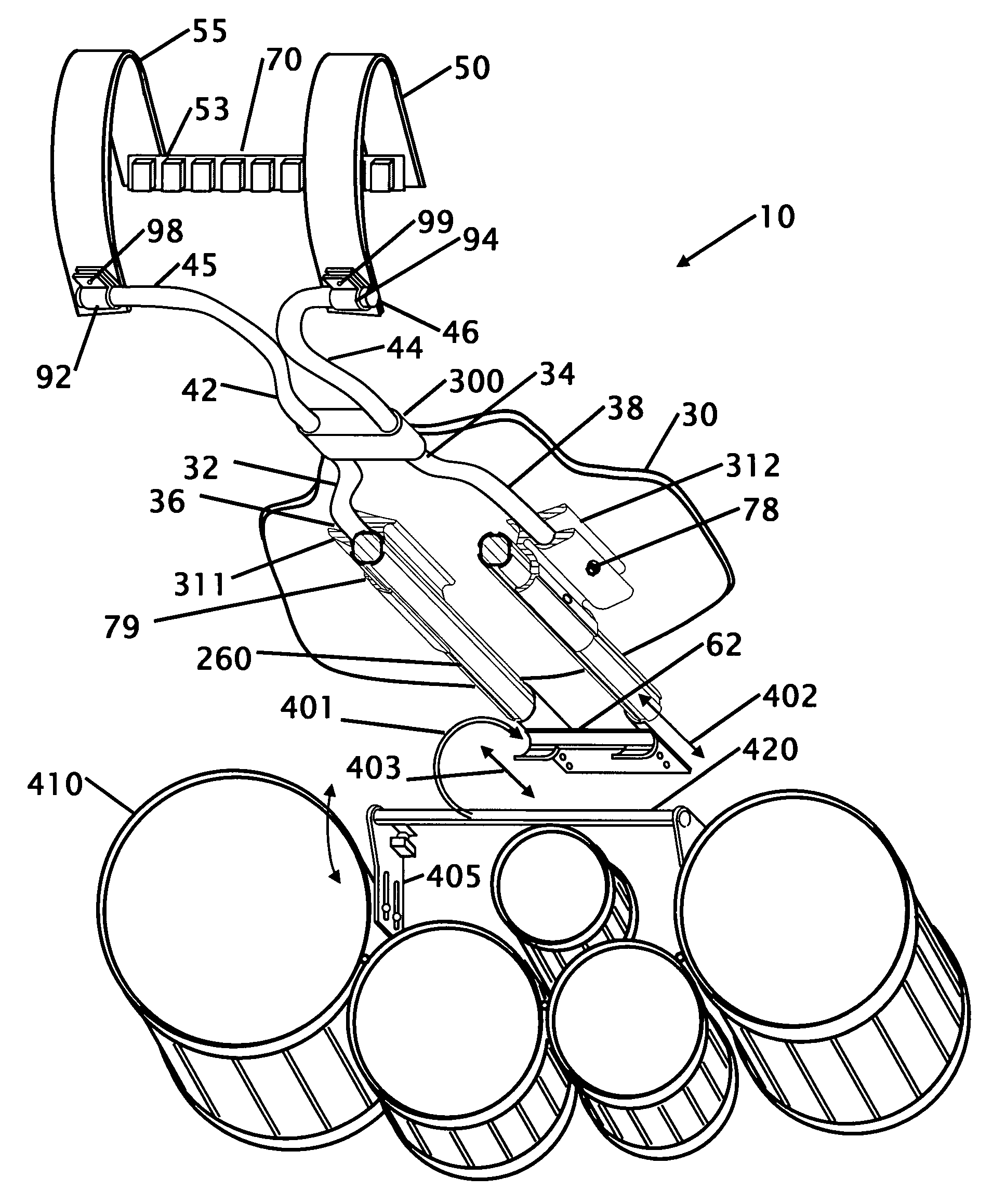
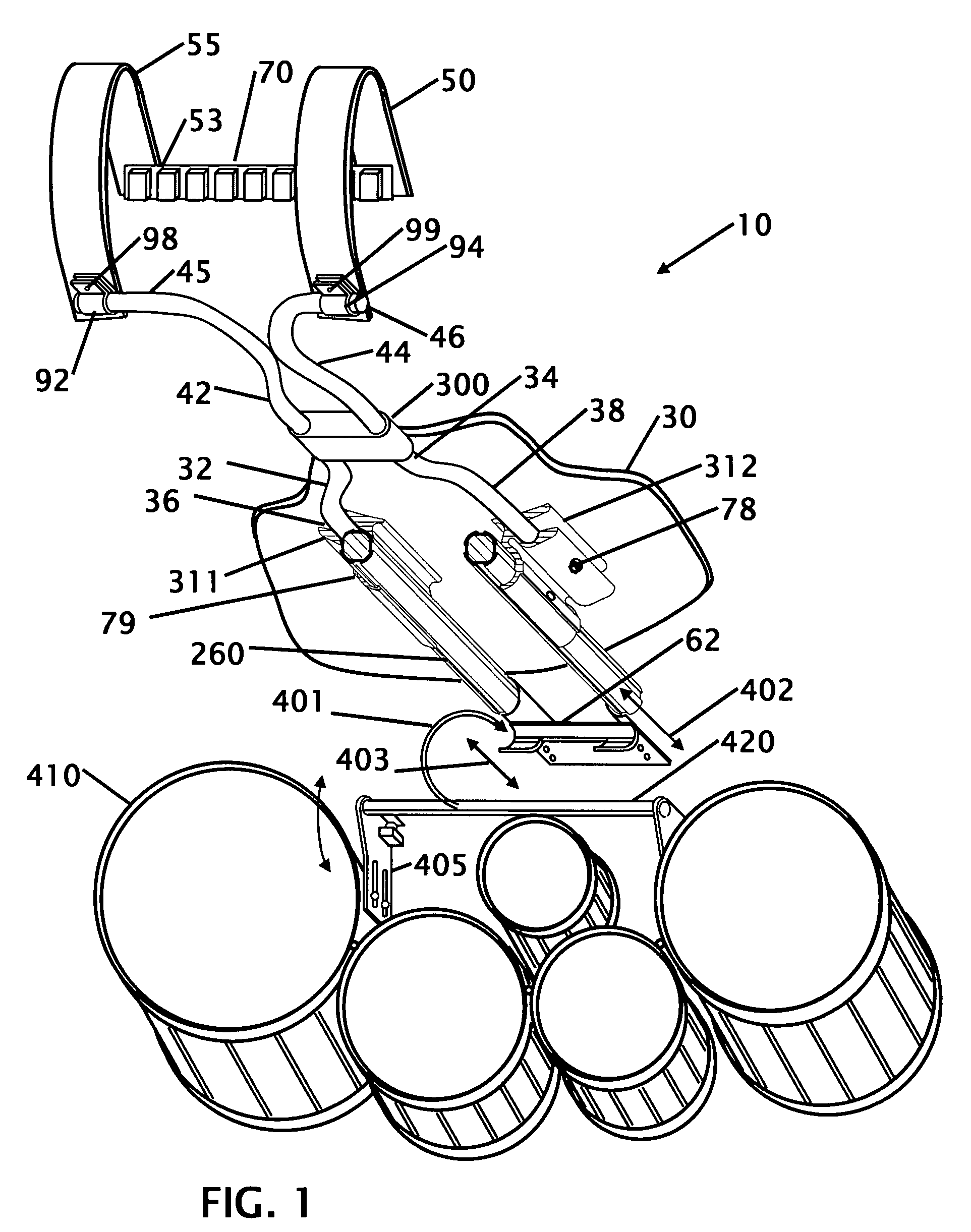
[0029]Referring to FIG. 1 shows an instrument carrier according to a first preferred embodiment. This figure shows a Tubular type carrier 10 for percussion instruments that comprises an abdomen plate 30, with lower support tubes or rods 32 and 34. The figure also has upper body vertical support rods or tubes 42 and 44 that are supported mid-span with a retainer 300. In the figure shown the coupler is a fixed member that holds the tubes in rigid position, but it is also contemplated that the coupler could be a hinge or an adjustable coupler that allows the distance between the upper and lower portions of the carrier to be adjusted as well as a single or compound hinged coupler that allows the carrier to be folded as shown in May U.S. Pat. No. 7,166,790 and May U.S. Pat. No. 6,323,407.

[0030]The lower rods or tubes 32 and 34 are bent where they independently spread to parallel portions 36 and 38 where they attach to supporting abdomen plate 30. Upper rods or tubes 42 and 44 having out-...


PUM


Abstract

An instrument carrier is disclosed for supporting one or more drums without using traditional “J” rods components. The carrier uses sliders that eliminate the interference with the user's legs and more particularly the user's thighs and provides a more natural stride of the user. The drum mounting structure is repositioned or translated on the sliders. The carrier allows the drum to be rigidly mounted in a variety of positions relative to the user. The cantilevered weight of the drum(s) rotates the drum or drum array to lock the drum(s) into a vertical or horizontal slots or saddle. In another embodiment a bridge extends from the carrier to a single post or tube to support a slidably mounted single drum. The structure also eliminates the necessity of a structurally rigid fixed abdomen plate and allows for use of a flexible and conforming abdomen plate.

Description

CROSS REFERENCE TO RELATED APPLICATION[0001]This application is a continuation-in-part of applicant's application Ser. No. 11 / 021,596 filed Dec. 23, 2004, now U.S. Pat. No. 7,326,842 that issued on Feb. 5, 2008 the entire contents of which is hereby expressly incorporated by reference herein.FIELD OF THE INVENTION[0002]This invention relates to a shoulder mounted percussion instrument carrier for one or an array of drums of various sizes. More particularly, the present invention relates to a carrier for one or more drums and replaces traditional “J” rods components. The elimination of the “J” rod components eliminates the interference with the user's legs and more particularly the user's thighs and provides a more natural stride of the user. Since the vertical or horizontal slots or saddle are not holes, that are commonly found with “J” rod carriers, the drum mounting structure can be repositioned or translated within the vertical or horizontal slots. The carrier allows the drum to ...

Claims


Application Information

Patent Timeline
Patent Type & Authority Patents(United States)
IPC IPC(8): A45F3/10
CPCG10G5/005
Inventor MAY, RANDALL, L.
Owner RANDALL MAY INT
Why Eureka
Eureka Blog
Learn More