
Monolithic ceramic end mill

Active Publication Date: 2014-02-11
KENNAMETAL INC
View PDF25 Cites 30 Cited by
  • Summary
  • Abstract
  • Description
  • Claims
  • Application Information

AI Technical Summary

Benefits of technology

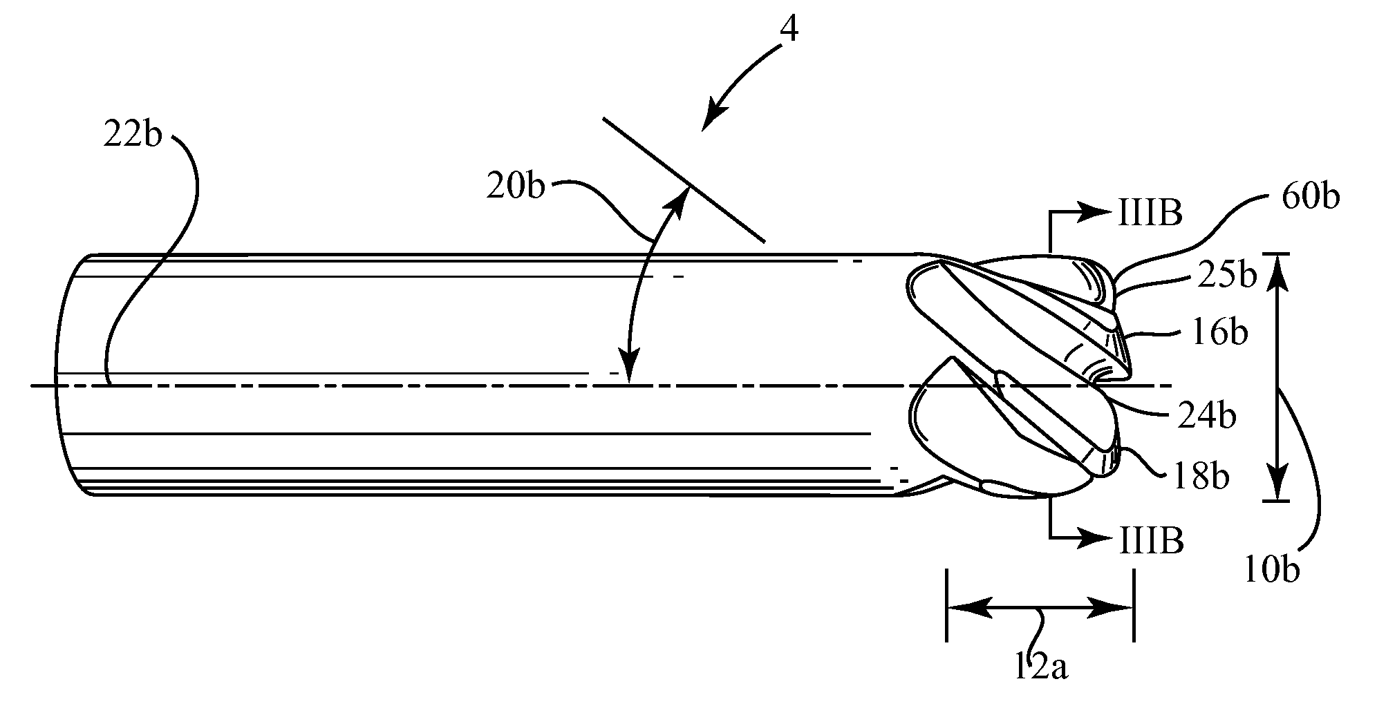
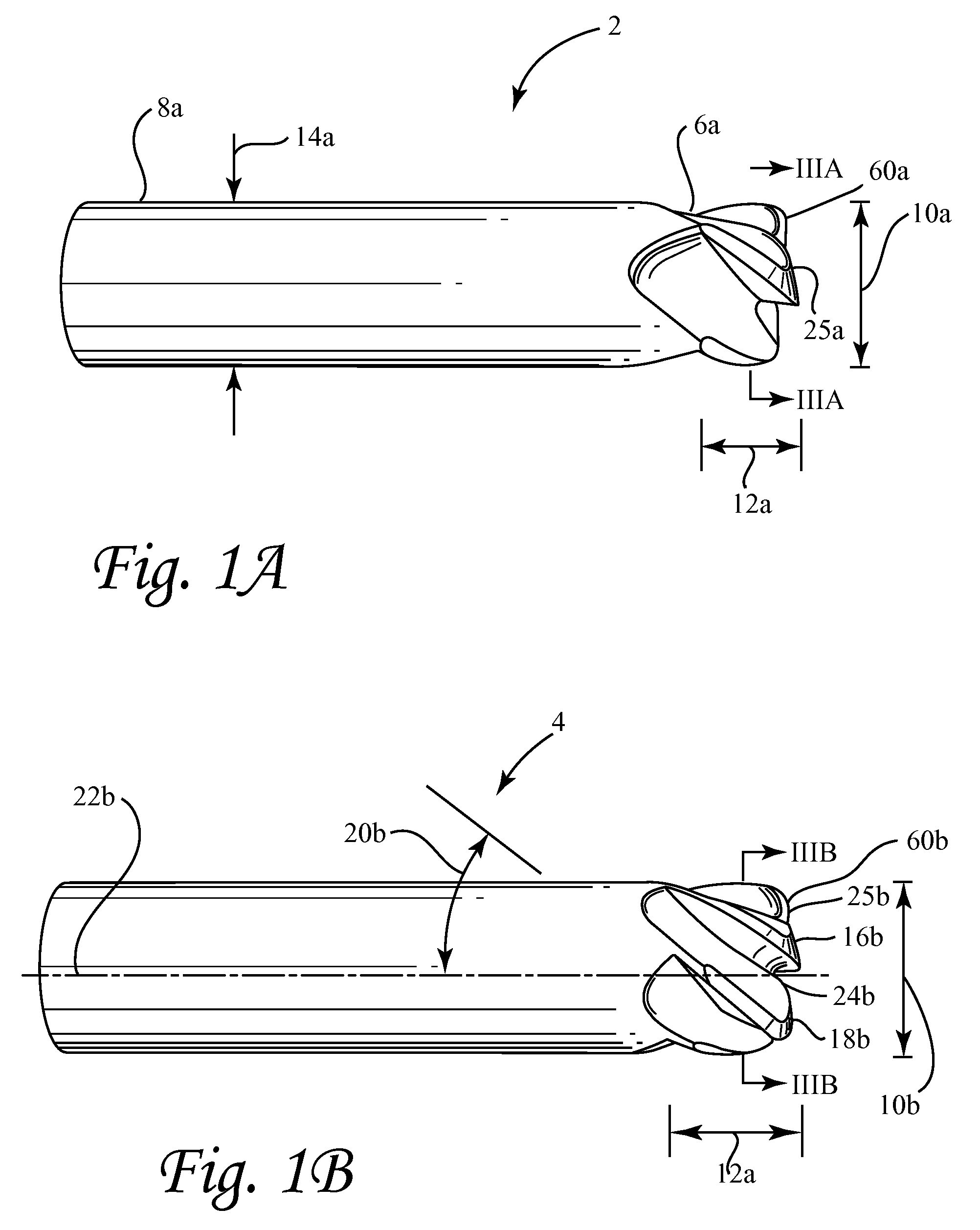
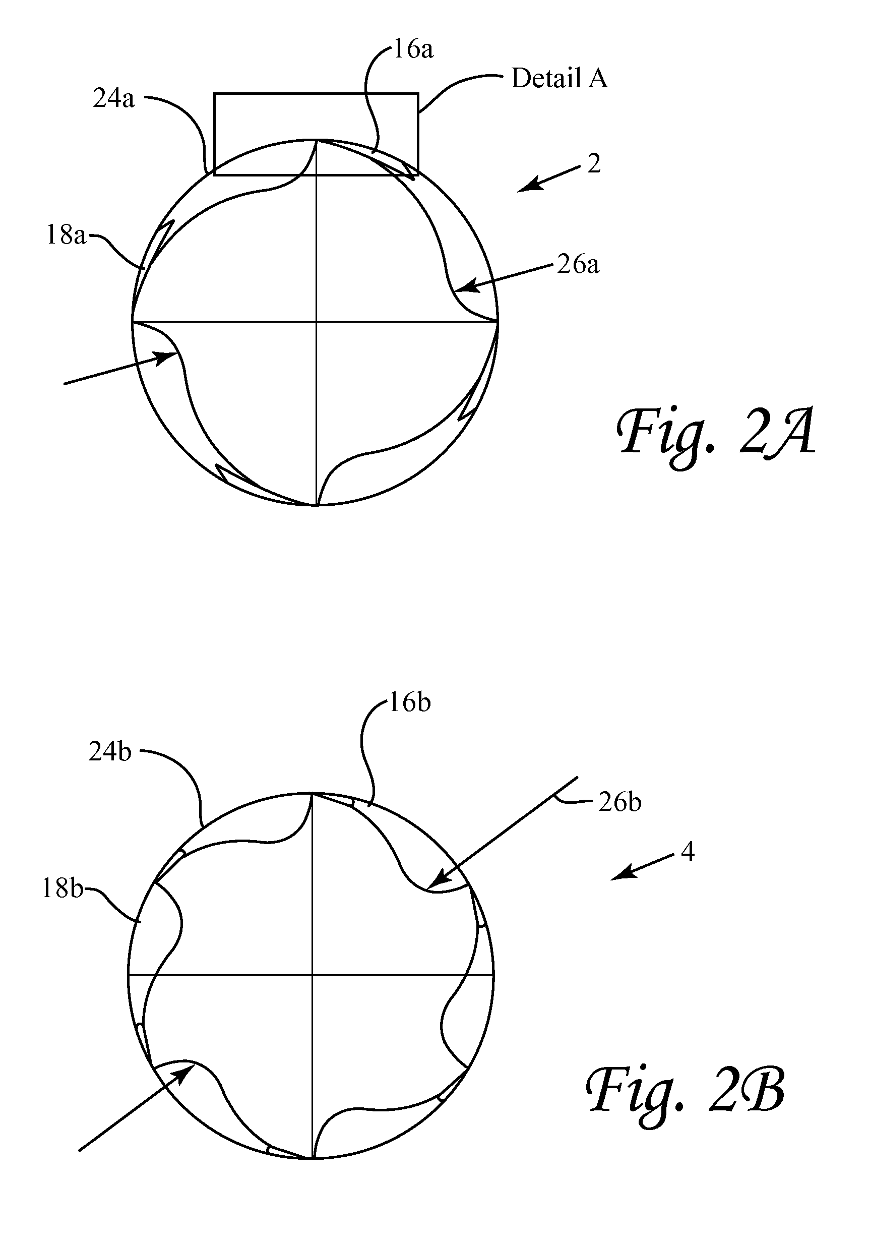
The present invention provides ceramic end mills that can be made in a single or dual end design. The cutting portions of these mills have specific lengths of cut and core sizes. They also feature negative radial rake cutting edges and helical flutes. The end mills have negative axial rake and are gashed before center. Additionally, the end mills have radiused corners and gashes that transition from radial to axial at a flute. The ceramic end mills are made of SiAlON ceramic. This invention also includes methods for using these ceramic end mills for materials milling.

Problems solved by technology

To the extent that ceramics have been used, due to their brittleness, they usually have been restricted to being employed as cutting edge inserts that are removably fixed to a body made of a more impact resistant material, e.g., a high speed steel.

Method used


Image

  • Monolithic ceramic end mill
  • Monolithic ceramic end mill
  • Monolithic ceramic end mill

Examples


examples 1-4

[0031]End mills Examples 1-4 according to embodiments of the present invention were machined from SiAlON to have the features described in Table 1.

[0032]

TABLE 1FeatureExample 1Example 2Example 3Example 4Overall length (mm)62.0062.0062.0062.00Shank diameter (mm)8.0012.008.0012.00Cutting diameter (mm)8.0012.008.0012.00Core diameter (mm)5.748.595.999.02Cutting length (mm)4.015.994.015.99Number of flutes4466Corner radius (mm)1.001.501.001.50Helical angle (degrees)40404040Radial rake (tangential−2−2−2−2degrees)Radial primary land0.330.480.330.48(mm)Radial primary relief8888angle (degrees)Radial secondary relief18181818angle (degrees)Axial rake (degrees)2222Axial primary land (mm)0.480.710.480.71Axial primary relief8888angle (degrees)Axial secondary relief18181818angle (degrees)Gash angle (degrees)27271818Endrake (degrees)5522Web thickness0.691.040.280.41(millimeters)Dish angle (degrees)2.52.522

example 5

[0033]An end mill according to the present invention having the dimensions of Example 3 was made from KYS30™ SiAlON and used to cut Inconel 718 without coolant at a high cutting speed of 720 meters / minute and a metal removal rate of about 14,500 mm3 / minute. The end mill was examined and found to have little chipping or metal buildup and had not reached its end of life. The radial facet wear was measured to be 0.4 mm.

examples 6-8

[0034]End mills according to the present invention having the dimensions of Examples 1 and 3 were made from KY1540™ SiAlON (Example 6), KYS30™ SiAlON (Example 7), and SP1300™ SiAlON (Example 8). Each was used to cut Inconel 718 at a low cutting speed of 300 meters / minute without a coolant at a metal removal rate of 5,150 mm3 / minute. After removing 2400 cubic millimeters of metal from the workpiece, each tool was examined and found to have little chipping or metal buildup and none had reached its end of life. The facet wear was measured to be 0.16 mm for Example 8 (SP1300™ SiAlON), 0.30 mm for Example 6 (KY1540™ SiAlON), and 0.40 mm for Example 7 (KYS30™ SiAlON).

[0035]These results were surprising because one would not have expected the SiAlON end mills that work well at high cutting speeds (as evidenced by Example 5) where chipping is the dominant factor in cutting life to also work well at low cutting speeds (as evidenced by Examples 6-8) where wear is the dominant factor. Furtherm...


PUM

PropertyMeasurementUnit
helical angleaaaaaaaaaa
gash angleaaaaaaaaaa
dish angleaaaaaaaaaa

Abstract

End mills are disclosed which may be made monolithically of ceramic or other materials. The cutting portions of the end mills have lengths of cut that are no more than twice their cutting diameters and cores which are at least 0.7 times their cutting diameters. Their axial blades have cutting edges with negative radial rake and are separated by helical flutes. Their cutting ends have negative axial rake and are gashed ahead of center and have radial cutting edges with negative rake. Such end mills also have radiused corners and gashes transitioning from radial to axial at a flute. Methods of milling materials using such ceramic end mills are also disclosed.

Description

FIELD OF THE INVENTION[0001]The present invention relates to monolithic end mills which may be made of ceramic and to methods of machining using such end mills.BACKGROUND OF THE INVENTION[0002]End mills are rotary tools that are used for machining many types of materials, from metals to plastics. They are supported by a shank which is generally cylindrical and adapted to be removably gripped by a motor driven chuck or functionally similar device. The shank graduates into a cutting portion on a single end end mill or into two cutting portions on a double end end mill. The cutting portion extends to an end of the end mill. The cutting portion has a plurality of cutting blades which are separated by flutes for carrying away the chips which are generated by the cutting operation. The cutting blades and the flutes may be parallel to the end mill's longitudinal axis, but more often are helical. The cutting portion typically terminates with radial cutting features designed to complement th...

Claims


Application Information

Patent Timeline
Patent Type & Authority Patents(United States)
IPC IPC(8): B23C5/10
CPCB23C2210/0421B23C2210/0428B23C2210/203B23C2210/24B23C2226/18B23C2210/205B23C2210/0435B23C2210/28B23C5/10Y10T407/1962Y10T407/27Y10T407/1946Y10T407/1948Y10T409/303752B23C5/1081B23C2210/0407B23C2210/0485B23C2200/00
Inventor DAVIS, DANNY R.LANDWEHR, SEAN E.YECKLEY, RUSSELL L.
Owner KENNAMETAL INC
Learn More