Electrical machine with multiple cooling flows and cooling method

a technology of electric machines and cooling ducts, applied in the direction of dynamo-electric machines, electrical equipment, supports/enclosements/casings, etc., can solve the problems of relatively complex mounting of permanent magnets in corresponding pockets in the rotor, and the high level of complexity in mounting has been accepted to date, so as to reduce the size of the cross section of the cooling ducts in the rotor, the effect of high efficiency and positive

Active Publication Date: 2014-02-11
FLENDER GMBH
View PDF27 Cites 6 Cited by
  • Summary
  • Abstract
  • Description
  • Claims
  • Application Information

AI Technical Summary

Benefits of technology

[0008]In one embodiment, the rotor is excited by permanent magnets. Therefore, the majority of losses are generally produced in the stator. The highly effective cooling of the stator according to the invention has an even more positive effect.
[0009]Only a single radial cooling slot preferably passes through the rotor. In general, fewer radial cooling slots can be provided in the rotor of the electrical machine according to the invention than in the prior art since an additional axial cooling flow ensures further heat removal. Nevertheless, an embodiment with only a single radial cooling slot in the rotor is particularly advantageous since the permanent magnets can then each be pushed into the rotor without problems from the end faces and encapsulated.
[0010]According to a further preferred embodiment, the axial first cooling ducts of the rotor are located on one side of the cooling slot, axial second cooling ducts (by way of their central axes) are located radially beneath the first cooling ducts in relation to the axis of the rotor, and axial third cooling ducts are located radially level with the first cooling ducts on the other side of the cooling slot, so that a third cooling flow can be routed through the second cooling ducts, the cooling slot and the radial cooling ducts separately from the second cooling flow. In this case, the center of the cooling flow is considered to be the reference point for the radial level (in relation to the rotor axis) of a cooling flow. Changing the cooling levels can advantageously have the effect that heat is removed even from that part of the rotor which is situated downstream by “unconsumed” cooling agent or cooling agent which has not yet been heated.
[0011]In addition to this, a fourth cooling flow can be provided which is introduced into the rotor radially level with the second cooling flow, is diverted in the rotor at a radial level beneath the second cooling flow and leaves the rotor at this deeper radial level. As a result, the flow of cooling agent which is already heated is routed toward the shaft after a certain axial distance, said flow of cooling agent no longer having to perform cooling tasks here. The third cooling flow can then take over the cooling tasks in this axial region.
[0012]The rotor can also have a pressure disk which has openings to the second or third cooling ducts, which openings are in each case smaller than the cross section of a second or third cooling duct. The volumetric flow rate of the cooling flows in relation to one another can be suitably adjusted by these openings, without the size of the cross section of the cooling ducts in the rotor being reduced.
[0013]Specifically, the stator can have a laminated core, and the cooling ribs can be formed by each individual lamination having corresponding projections which project outward. As a result, a laminated stator core with external cooling ribs can be manufactured in a very simple manner since the cooling ribs are already “punched” onto the laminated core. An alternative would involve welding the external cooling ribs onto the laminated stator core. However, welding constitutes an additional working step which can be avoided.

Problems solved by technology

If the electrical machine is a so-called permanent magnet generator, mounting of the permanent magnets in corresponding pockets in the rotor is relatively complex if the rotor has a large number of radial ventilation slots.
However, in order to be able to guarantee an adequate amount of heat is removed, the high level of complexity in respect of mounting has been accepted to date.

Method used


Image

  • Electrical machine with multiple cooling flows and cooling method
  • Electrical machine with multiple cooling flows and cooling method

Examples


Embodiment Construction

[0015]The exemplary embodiments described in greater detail below are preferred embodiments of the present invention.

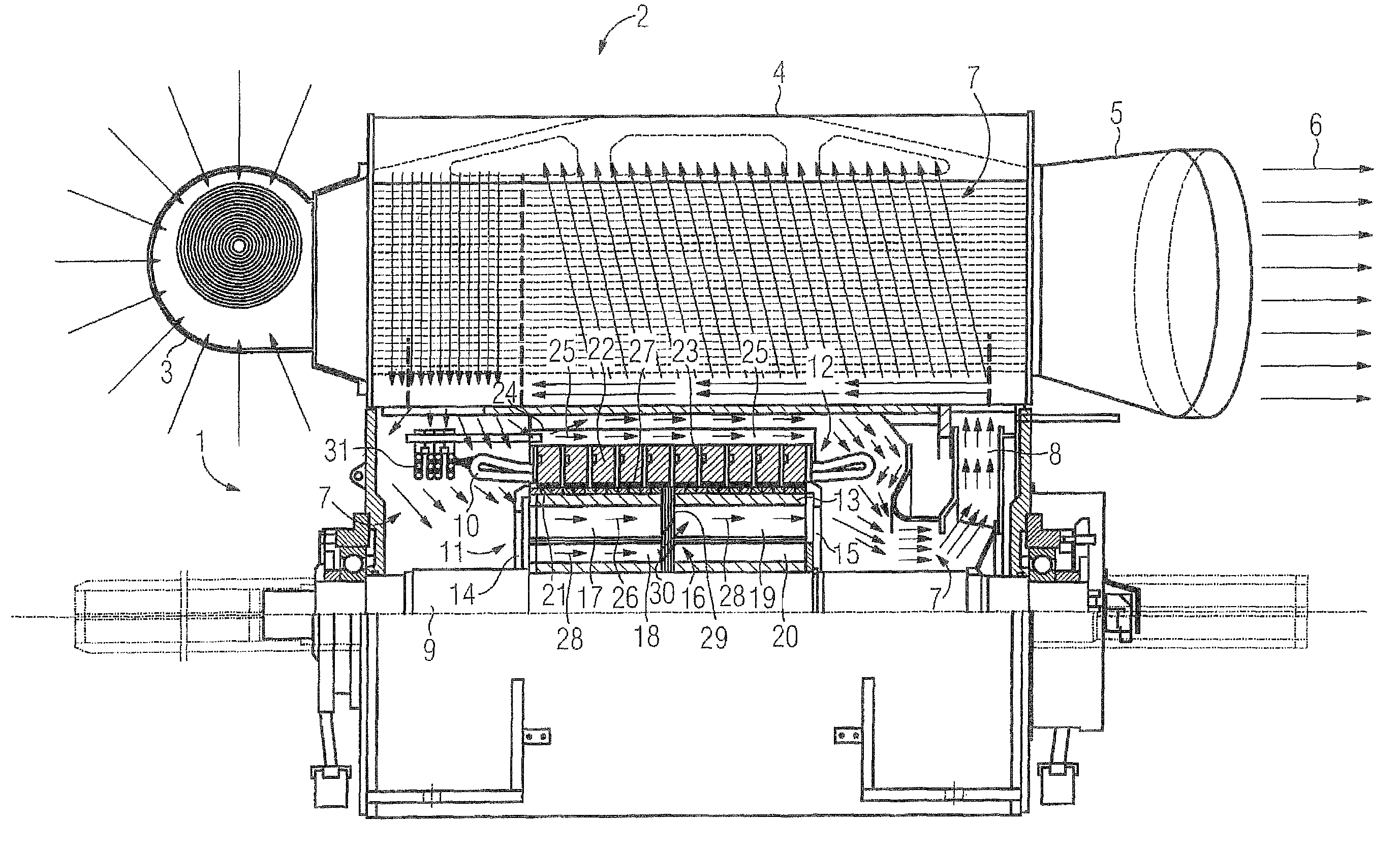
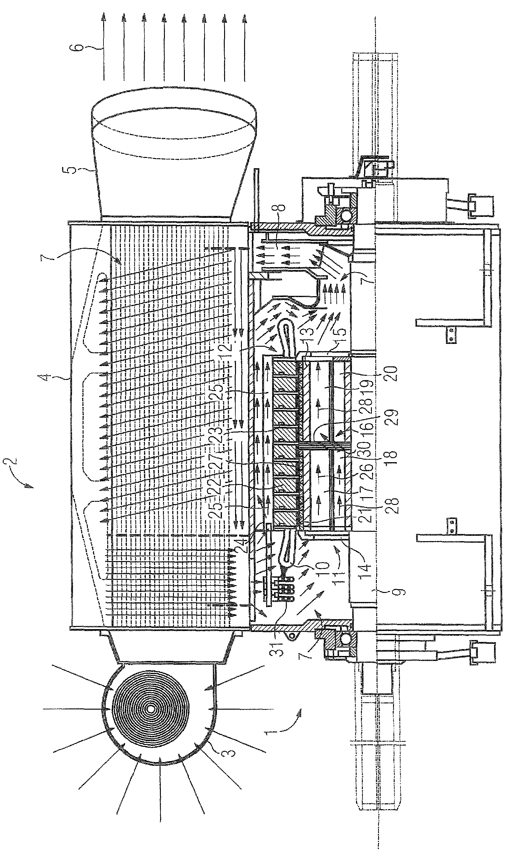
[0016]The FIGURE shows a generator 1 having a cooling device 2. The cooling device 2 has a fan 3 for drawing in cooling air which it blows into a heat exchanger 4. The air flows from there to the outside through an outlet nozzle 5. This defines an external cooling circuit.

[0017]The heat exchanger 4 cools an internal, closed cooling circuit 7 using the external cooling circuit 6. The internal cooling circuit 7 is driven by a shaft-mounted fan 8 which is mounted on the B-side of the shaft 9 of the generator 1. The inner cooling circuit flows through the heat exchanger starting from the fan 8 and enters the winding overhang space on the A-side (drive side) of the generator. Here, said internal cooling circuit flows around the winding overhang 10 and the winding circuit 31 and then flows through the rotor 11 and the stator 12, as will be explained in greater detail below....


PUM


Abstract

An electrical machine with a stator has a winding support, which has at least one radial cooling slot, and a rotor, which likewise has at least one radial cooling slot. The winding support of the stator has on its outer shell a number of axially running cooling ribs, along which an axially running first cooling flow can be directed. Furthermore, the rotor has axially running first cooling ducts, which open out into its at least one radial cooling slot, so that a second cooling flow can be directed in the axial direction along the axial cooling ribs of the stator through the axial first cooling ducts of the rotor, the at least one radial cooling slot of the rotor, the air gap between the rotor and the stator and the at least one radial cooling slot. In this way, the stator can be cooled by two different cooling flows.

Description

CROSS-REFERENCES TO RELATED APPLICATIONS[0001]This application is the U.S. National Stage of International Application No. PCT / EP2009 / 065737, filed Nov. 24, 2009, which designated the United States and has been published as International Publication No. WO 2010 / 072499 and which claims the priority of German Patent Application, Serial No. 10 2008 064 495.1, filed Dec. 23, 2008, pursuant to 35 U.S.C. 119(a)-(d).BACKGROUND OF THE INVENTION[0002]The present invention relates to an electrical machine having a stator which has a laminated core which has at least one radial ventilation slot, and having a rotor which likewise has at least one radial ventilation slot. The present invention also relates to a method for cooling an electrical machine of this kind.[0003]Radially running cooling slots are often provided both in the rotor and in the stator of electrical machines in order to remove heat from the rotor and the stator. If the electrical machine is a so-called permanent magnet generat...

Claims


Application Information

Patent Timeline
Patent Type & Authority Patents(United States)
IPC IPC(8): H02K5/18H02K9/18H02K5/20H02K9/00H02K9/02
CPCH02K9/10
Inventor MEMMINGER, OLIVERSCHOBERL, FRIEDRICHSCHONBAUER, NORBERTSTEGNER, JOHANNDANNER, ROBERTDRABER, JURGENFRIEDL, DANIELVOGEL, ANATOLI
Owner FLENDER GMBH
Why Eureka
Try Eureka