Methods for creating developable surfaces

Active Publication Date: 2014-02-11
DAEDAL DOODLE
View PDF12 Cites 10 Cited by
  • Summary
  • Abstract
  • Description
  • Claims
  • Application Information

AI Technical Summary

Benefits of technology

[0028]In one aspect, the present invention provides several techniques that allow developable surfaces to be constructed and assembled faster and cheaper, thus facilitating the construction of 3D models that are significantly more valuable than what is achievable with existing state-of-the-art techniques. Whereas the seams between the developable surface parts have been a weakness of existing techniques, a new approach allows the surface geometry to be stylized intentionally for visual appeal: the seams are an integral, desirable part of the final 3D object. Adding further appeal to the output models, textures, such as photos from a digital camera, can be placed on the 3D shape independently of the developable surface boundaries. The combined contribution of these complementary techniques provides unprecedented customization of the appearance of developable surfaces.
[0033]The new techniques are integrated into a significantly modified workflow compared to that described in the above patent application. A modified workflow has been selected to support low cost experimentation over multiple design cycles. The workflow can be fully automated, but, since aesthetics of the output models is a priority, a graphical user interface for enhanced control and instructive feedback is an integral part of the system.
[0045]The workflow in one embodiment starts with initialization of evolution parameters and a network of curves constrained during evolution to a surface, i.e., a 2D evolution space. The curves are assumed to be arbitrary curves which are sampled discretely as piecewise linear curves, or polylines. Optionally, attributes and dimensions of the output material(s) may be specified as well. The user is allowed to edit the curves and parameters. The curve network may define bounded regions on the evolution surface, which will henceforth be referred to as loops. The loops may approximate parts of the surface(s). In some embodiments, some curves (or portions of curves) may not be constrained to the evolution surface and may float unconstrained in 3D space. Since the generalization to curve networks comprising both constrained and unconstrained curves is straightforward, we will, without loss of generality, refer to curves on a surface as if all its points were constrained. One or more curve loops may be tessellated to form tessellated loops (or strips). The tessellation may be performed using triangles and / or quadrilaterals, possibly connected by planar polygons at junctions between branches, where the polygons have five or more sides. The tessellation is subsequently developed (i.e., unrolled) onto a plane, yielding an unfolded tessellation with the same number of polygons, the same angles and areas of the polygons, and the same topology (i.e., the same shared edges between the polygons). Once a loop is specified, it can be assigned material properties. If the loops are to be manufactured in materials of different colors, for example, they should be marked as such and assigned to a material sheet with these properties. The term “material sheet” will be used to refer to an individual piece of flat material that is used to manufacture one or more developable strips. If an unfolded loop overlaps itself, other loops, or the boundaries of its material sheet, it can not be manufactured in one piece. The method detects overlaps between loops and unfolded loops (i.e., in both 3D and 2D) and eliminates them during evolution. In post-evolution processing a set of loops are prepared for manufacturing by adding appropriate devices to enable the assembly of the manufactured surfaces, as well as support for textural information. Finally, the finished data is evaluated prior to manufacturing. The workflow enables the user to go back at any time and continue the curve evolution and editing. Data added during post-evolution processing will generally persist during such iterations.

Problems solved by technology

However, their scope is limited due to several factors, including tedious assembly and detracting visual artifacts in the assembled 3D object.
On the other, the cost of the manufacturing generally increases with the complexity of the geometry.
The techniques described and depicted in U.S. Pat. No. 6,819,966 require too much tedious manual work to be practical for assembly of models of the geometric complexity that would be required to make the output models sufficiently appealing to be feasible to produce on a larger scale.
Many such solutions have been proposed, but they suffer from the following shortcomings:Limited control over the number of developable surfaces.Limited control over the shape of the developable surfaces.Limited control over the regularity of the developable surfaces.Lack of attention to the ease-of-assembly of the developable surfaces.Lack of attention to perceptual aspects of the aesthetics of the developable surfaces.Most existing developable surface techniques aimed at organic shapes represent surfaces as infinitely thin manifolds, ignoring the fact that real-world materials have a non-zero thickness.
In terms of the output surfaces, there is an important tradeoff:Short developable surface strips are problematic because:They produce a large number of developable surfaces that complicate the assembly.Short strips make it difficult or impossible to create stylized developable surfaces where seams appear as long, flowing curves.Long developable strips lead to two problems:Self-intersections occur after unfolding them into a plane, making it impossible to manufacture strips in one piece.Irregular shapes may be difficult to pack optimally into a piece of planar material.Combinations of long, short, small, and large developable surfaces will not appear visually attractive unless careful attention is paid to the overall structure of the network of developable patches.
As a result, developable surfaces have seen limited use in the manufacturing of organic 3D geometry.

Method used


Image

  • Methods for creating developable surfaces
  • Methods for creating developable surfaces
  • Methods for creating developable surfaces

Examples


Embodiment Construction

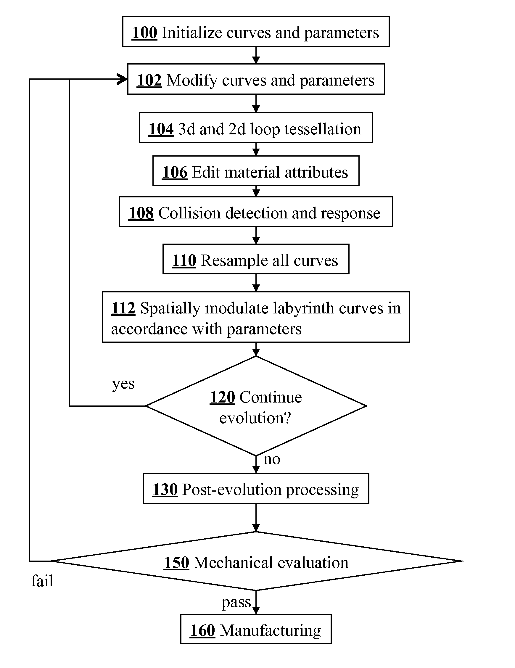
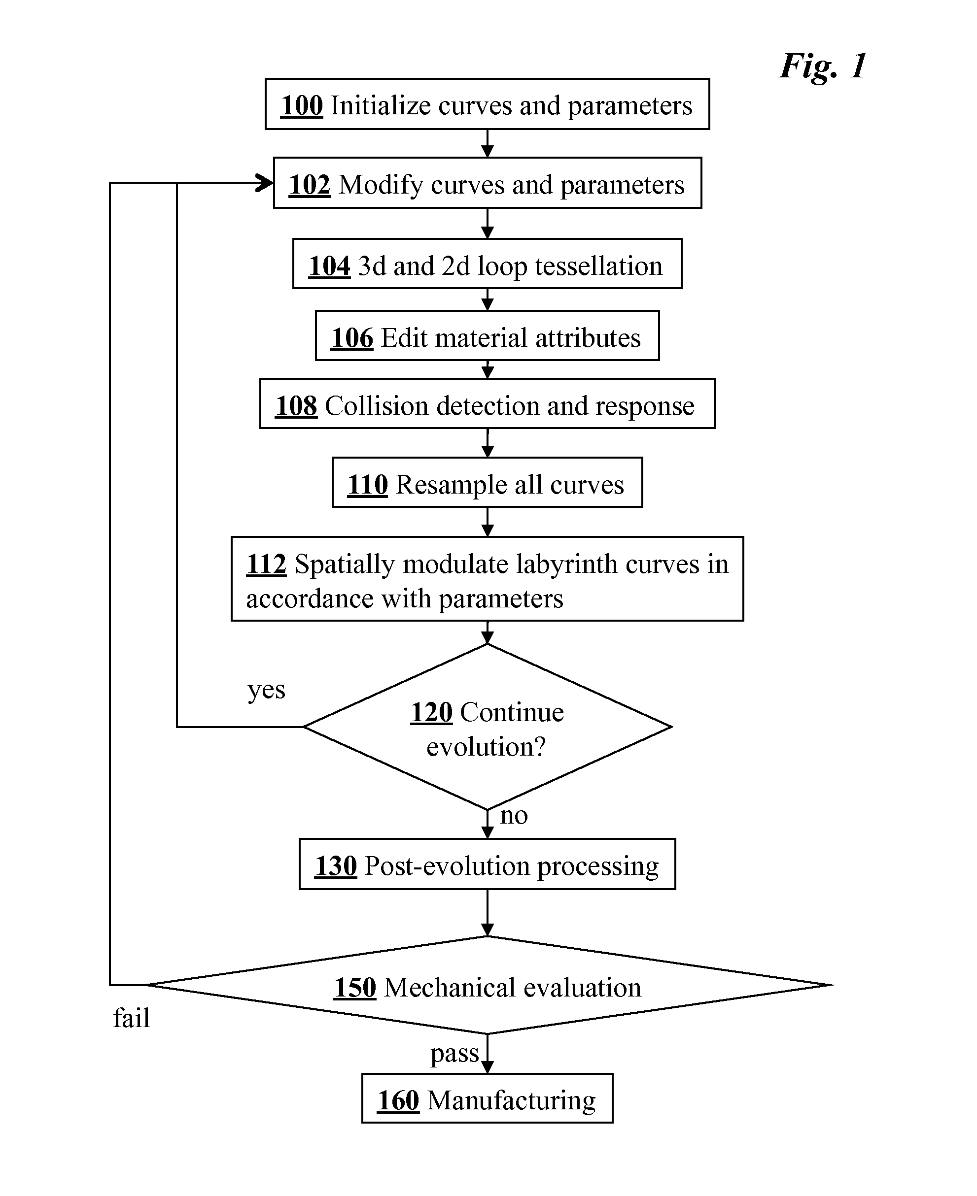
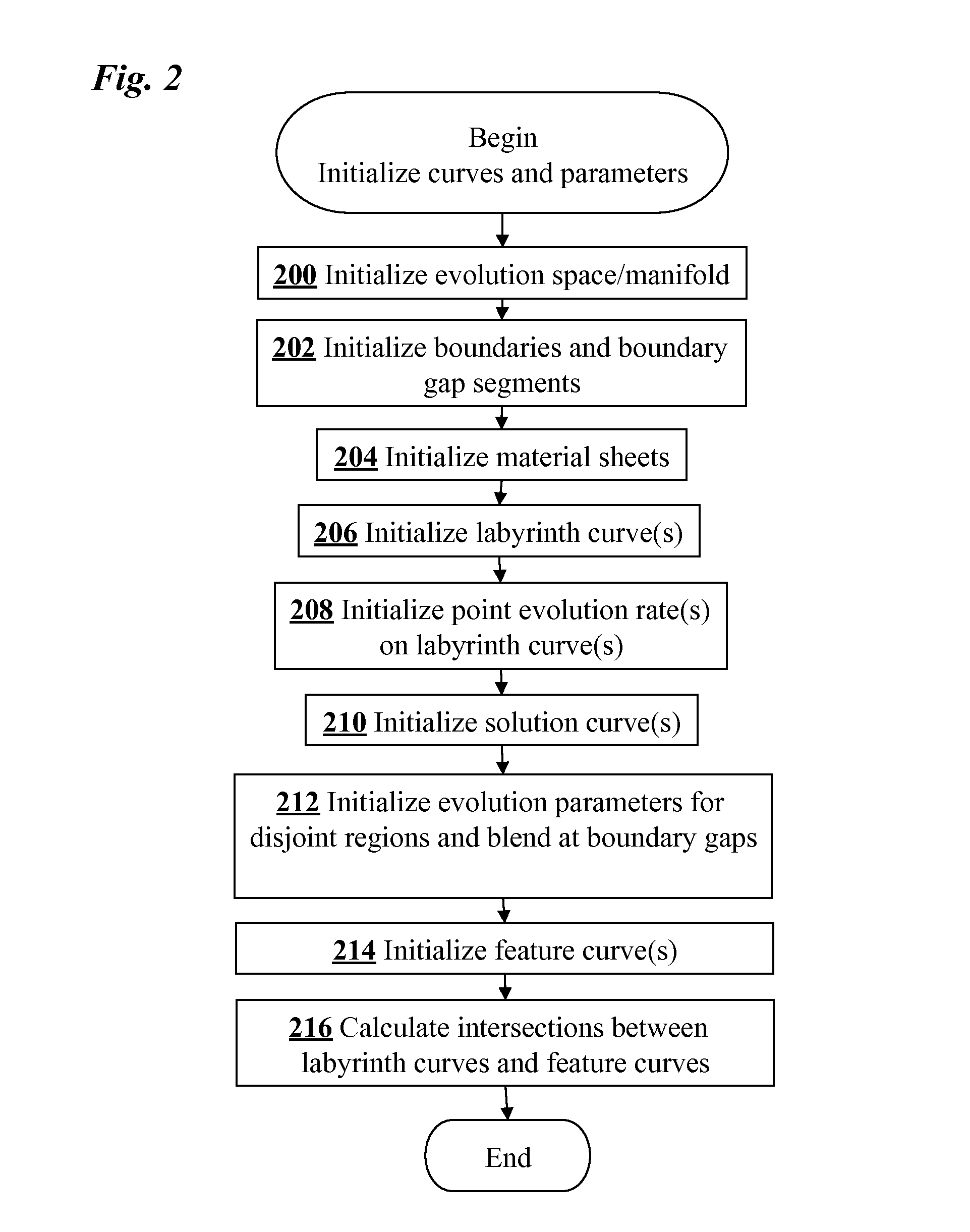
[0145]Main steps of a method for generating textured developable surface sculptures according to an embodiment of the present invention are shown in FIG. 1. The process starts with the initialization of curves and parameters, step 100, which is shown in more detail in FIG. 2. First, the evolution space / manifold is initialized in step 200. In addition to a geometric description, the evolution space may comprise texture information. These textures may be stored in the form of 2D texture maps associated with the evolution space, 2D texture maps associated with other texture surfaces, or 3D textures, including procedural textures defined on volumetric regions containing the evolution space. In step 202, the boundaries and boundary gap segments, which are explained in more detail in US PG Publication No. 20080297514, are initialized. In a preferred embodiment, the system analyzes the curve network and gives preliminary recommendations for changes that might improve the strength of the fi...


PUM


Abstract

Developable surfaces are generated by interactively evolving curves on a 2D surface embedded in 3D space using an iterative process to produce a model for the construction of a stylized three dimensional sculpture. Each iteration includes tessellating loops formed by the curves on the surface and unfolding the resulting tessellated strips onto a 2D plane. Collisions between the unfolded tessellated strips in 2D and between the loops in 3D are resolved, and the rendered evolved curve in 3D and tessellated strips in 2D are displayed simultaneously during the evolution. A graphical user interface allows the curve network, tessellated strips, and curve evolution parameters to be modified by a user. 2D textures may be mapped to the unfolded tessellated strips, and a set of tool paths may be output for cutting a 2D material.

Description

CROSS-REFERENCE TO RELATED APPLICATIONS[0001]This application claims priority from U.S. Provisional Patent Application 61 / 335,902 filed Jan. 12, 2010, which is incorporated herein by reference.FIELD OF THE INVENTION[0002]The present invention relates generally to computer graphics and computer assisted design techniques. More specifically, it relates to interactive computer-implemented methods for generating digital developable surface models and associated articles of manufacture.BACKGROUND OF THE INVENTION[0003]Developable surfaces are three-dimensional (3D) objects formed from two-dimensional (2D) surfaces that can be flattened to a plane without stretching the surface material; simple examples include the cylinder, the cone, and ruled surfaces. Developable surfaces are important in manufacturing because they can be created from pre-fabricated flat materials, such as paper, textiles, or sheet metal. They have been ubiquitous in engineering applications for centuries and there is ...

Claims


Application Information

Patent Timeline
Patent Type & Authority Patents(United States)
IPC IPC(8): G06T17/20G09G5/00G06T15/10G06T15/20G06T15/30G06F19/00G06T15/00
CPCG06T19/00G06T2219/021G06T17/20
Inventor PEDERSEN, HANS, KOHLING
Owner DAEDAL DOODLE
Why Eureka
Try Eureka