Method and device for supervising secondary circuit of instrument transformer in power system

a secondary circuit and transformer technology, applied in the field of power systems, can solve the problems of unwanted operation of various protection functions of ied, differential protection functions may mal-operate, and unwanted operation of various protection functions, and achieve the effect of small amount of information and more reliable and sensitive performan

Inactive Publication Date: 2014-02-11
ABB POWER GRIDS SWITZERLAND AG +2
View PDF6 Cites 1 Cited by
  • Summary
  • Abstract
  • Description
  • Claims
  • Application Information

AI Technical Summary

Benefits of technology

[0017]An object of the present invention is to provide a novel method and device for current / voltage circuit supervision with more reliable and sensitive performance and small amount of information to be collected, thus prevent unwanted operation of relevant protection functions.
[0025]By utilizing integrated information which is available via IEC 61850, the current / voltage circuit supervision solutions according to embodiments of the present invention provide more reliable and sensitive performance and very small amount of information needs to be collected.

Problems solved by technology

However, failures may happen in the secondary circuits between the VT and the IED (this condition is referred to as VTfailure in the description) or between the CT and the IED (this condition referred to as CTfailure in the description), and result in unwanted operations of various protection functions of the IED.
For example, VTfailure may cause a distance protection function to mal-operate.
On the other hand, in the case of a CTfailure, a ‘false’ differential current will appear on the phase of CTfailure, and if the magnitude of this ‘false’ differential current is bigger than a startup threshold, the differential protection function may mal-operate.
Furthermore, single-phase or double-phase CTfailure will result in a ‘false’ negative sequence current or zero sequence current, which will cause unwanted operations of negative / zero sequence current based protections.
Consequently this method increases the complexity of the hard wiring, and thus decreases the reliability of the IED.
Furthermore, this method can not detect 3-phase CTfailure because under such conditions, there will be no zero sequence current in both windings or both current transformers.
However, this method can not detect 3-phase CTfailure because it is based on zero sequence measurements.
Secondly, it can not work properly during asymmetrical operation condition (e.g. single-pole reclosing period) because there are always both zero sequence current and zero sequence voltage.
Thirdly, it may mal-operate if the zero sequence impedance of the system is very small.
Moreover, sometimes the voltage inputs are even not available.
However, when a fault occurs on a line that connects the power source and the load, the protection IED on the load side may also detect the sudden disappearance of the phase current, thus the CTfailure supervision function will operate incorrectly.
This method, however, requires sampled data from all the power system components (lines, transformers, etc) that are connected to the protected busbar, which means large amount of communication traffic and slow operation speed.
Furthermore, it is not applicable during asymmetrical operation conditions (e.g., single-pole reclosing period).
This method can not detect 3-phase VTfailure.
It can not work properly during unsymmetrical operation condition because there are always both zero / negative sequence current and zero / negative sequence voltage.
This method needs measured voltages from two sets of secondary windings, which increases the complexity of the hard wiring, and thus decreases the reliability of the IED.
Furthermore, the above mentioned current / voltage circuit supervision methods based on both voltages and currents will fail if failures occur simultaneously on both current and voltage secondary circuits.
As shown in the above description, the existing methods either are unreliable under certain conditions or rely on large amount of communication.

Method used


Image

  • Method and device for supervising secondary circuit of instrument transformer in power system
  • Method and device for supervising secondary circuit of instrument transformer in power system
  • Method and device for supervising secondary circuit of instrument transformer in power system

Examples


embodiment 1

[0043]This embodiment of the present invention complies with principle 1, and will be explained by taking voltage circuit supervision as an example.

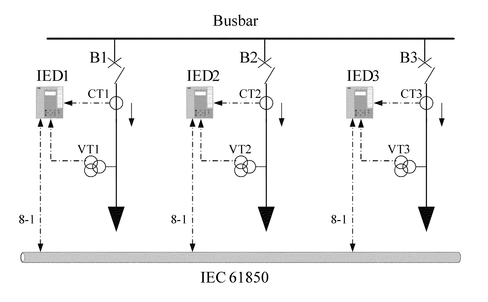
[0044]A voltage circuit supervision method according to the embodiment of the present invention will be described hereunder with reference to FIGS. 3 and 5. FIG. 3 is a diagram illustrating a secondary system configuration according to an embodiment of the present invention. In FIG. 3, protection IEDs IED1, IED2 and IED3 are connected to VT1, VT2 and VT3 respectively and each protects a power system component (not shown) respectively. The three power system components are connected to the same busbar and are all in operating condition. The breakers B1, B2 and B3 are designed to switch on / off the connections between the power system components and the busbar respectively. FIG. 5 is a flow chart illustrating a method according to an embodiment of the present invention.

[0045]In the preferred embodiments of the present invention, each protec...

embodiment 2

[0053]This embodiment of the present invention complies with principle 2, and will also be explained by taking voltage circuit supervision as an example.

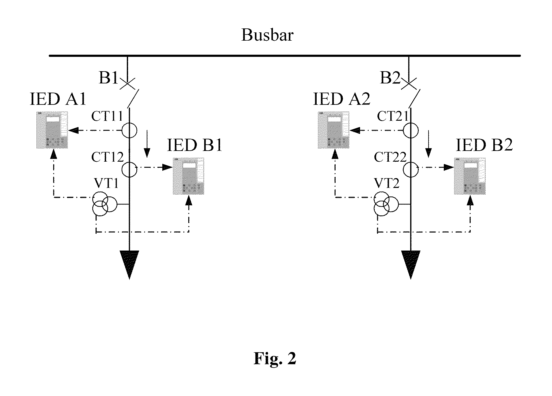
[0054]In this embodiment, a voltage circuit supervision method according to the embodiment of the present invention will be described hereunder with reference to FIGS. 4 and 5. FIG. 4 is a diagram illustrating a secondary system configuration for dual protection IEDs according to another embodiment of the present invention. In FIG. 4, two protection IEDs, IED A1 and IED B1, are provided to protect a power system component (not shown) and two protection IEDs, IED A2 and IED B2, are provided to protect another power system component (not shown). The two power system components are connected to the same busbar. IED A1 is connected to a current transformer CT11 and a first secondary winding of a voltage transformer VT1. IED B1 is connected to a current transformer CT12 and a second secondary winding of the voltage transformer VT1. IED A...

embodiment 3

[0063]This embodiment of the present invention will be explained by taking current circuit supervision as an example.

[0064]This embodiment provides a current circuit supervision method in a power system with a secondary system configuration as shown in FIG. 3. The supervision method according to this embodiment is almost identical to that in Embodiment 1, except that in the method of this embodiment for supervising current circuit, what to be detected by the protection IEDs is a current disturbance. Accordingly, the messages communicated between the protection IEDs are designed slightly differently. Consequently, the detailed procedure of the supervision method will not be repeated.


PUM


Abstract

A method and a protection IED for supervising a secondary circuit of an instrument transformer in a power system are disclosed. The instrument transformer is connected to a power system component. The method includes: detecting, by a protection IED which is connected to the secondary circuit of the instrument transformer and protects the power system component, disturbances in a signal from the instrument transformer; and determining whether a failure occurs in the secondary circuit of the instrument transformer, according to both a disturbance detection result from the protection IED and another disturbance detection result from at least one of other protection IEDs. The other protection IEDs include protection IEDs which are connected to other secondary circuits of the instrument transformer or to secondary circuits of another instrument transformer connected to the power system component, and protection IEDs which are connected to other instrument transformers connected to other power system components connected to the same busbar as the power system component is connected to. The secondary circuit supervision solutions provide more reliable and sensitive performance and need very small amount of information to be collected.

Description

RELATED APPLICATION[0001]This application is a national filing of PCT application Serial No. PCT / CN2008 / 072480, filed Sep. 24, 2008.FIELD OF INVENTION[0002]The present application relates to the field of power system, and more particularly, to a method and device for supervising a secondary circuit of an instrument transformer in a power system.BACKGROUND OF THE INVENTION[0003]Instrument transformers are used to step-down current or voltage to measurable values, and are widely used in various power systems. There are two basic types of instrument transformers, i.e. voltage transformer and current transformer. A voltage transformer (VT, in the description also including Capacitive Voltage Transformer, CVT) is designed to reproduce accurately the primary voltage on the secondary side, while a current transformer (CT) is for current signals. The correct information about the primary values of voltages (from VT) and currents (from CT) are the basis for the correct operation of an intell...

Claims


Application Information

Patent Timeline
Patent Type & Authority Patents(United States)
IPC IPC(8): H02H7/04
CPCH02H3/40H02H3/05H02H7/261G01R31/027G01R31/62
Inventor SU, BINFAN, JIANZHONGJING, LEILIU, QIANJINWANG, JIANPINGYANG, YING
Owner ABB POWER GRIDS SWITZERLAND AG
Why Eureka
Try Eureka