
Manufacture of lattice truss structures from monolithic materials

Active Publication Date: 2014-02-18
UNIV OF VIRGINIA ALUMNI PATENTS FOUND
View PDF5 Cites 20 Cited by
  • Summary
  • Abstract
  • Description
  • Claims
  • Application Information

AI Technical Summary

Benefits of technology

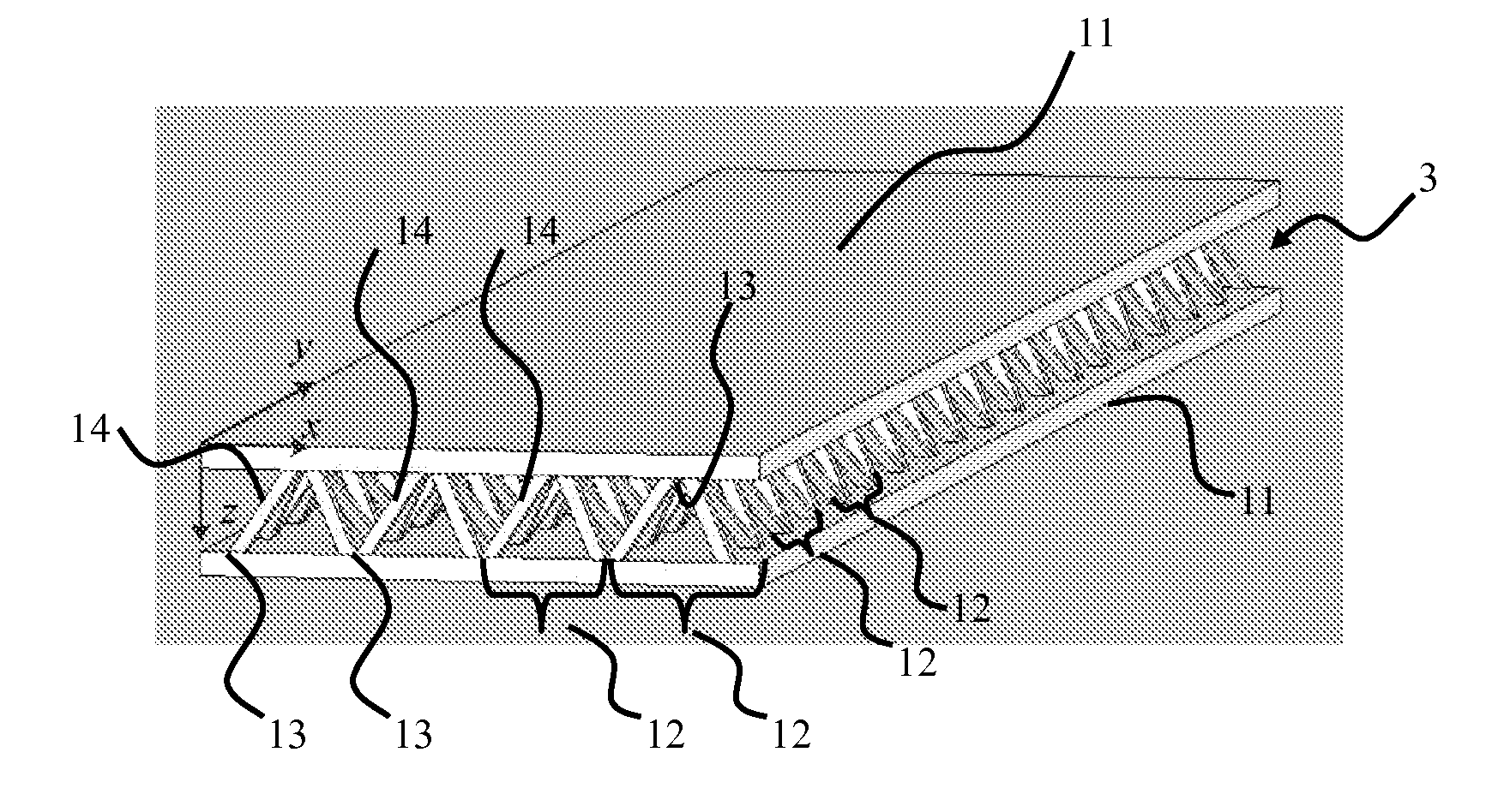
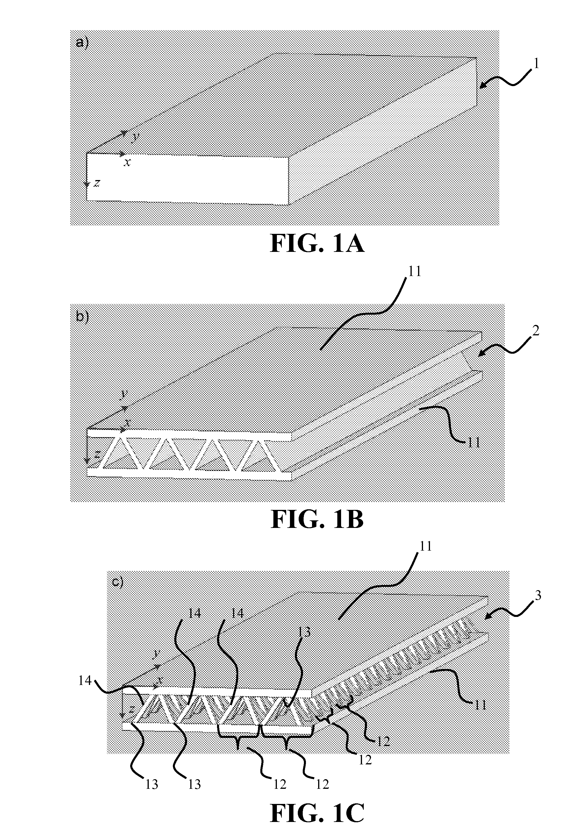
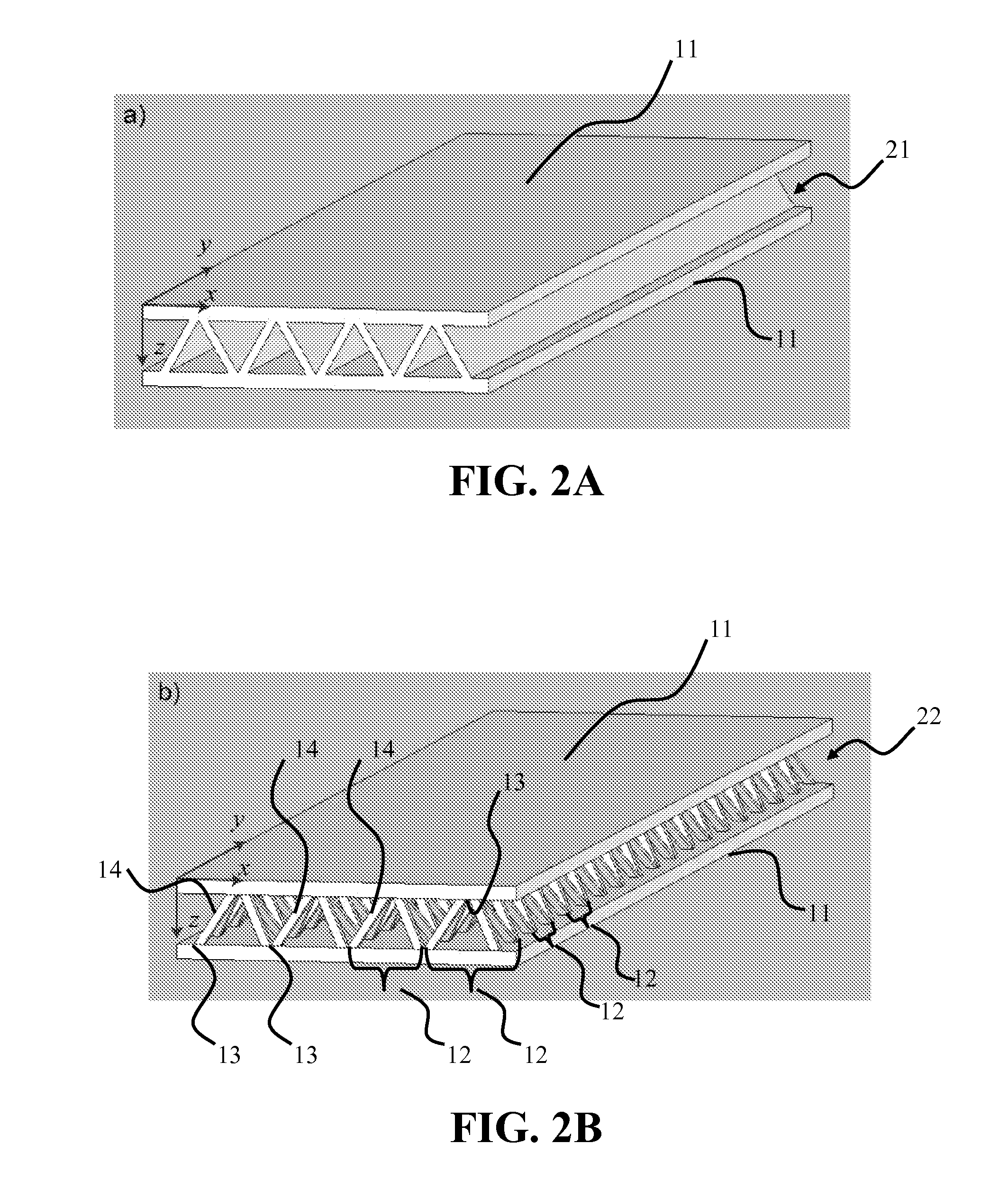
[0010]Provided herein are exemplary methods and systems to manufacture lattice-based sandwich structures from monolithic material. Such methods and systems eliminate the bonding process which is conventionally used to join lattice based truss cores to facesheets to form sandwich structures. This bonded interface is a key mode of failure for sandwich structures which are subjected to shear or bending loads because the nodes transfer forces from the face sheets to the core members while the topology for a given core relative density dictates the load carrying capacity (assuming adequate node-bond strength exists).
[0011]An aspect of an embodiment of the present invention comprises a core and related structures that provide very low density, good crush resistance and high in-plane shear resistance. An aspect of the truss structures may include sandwich panel cores and lattice truss topology that may be designed to efficiently support panel bending loads while maintaining an open topology that facilitates multifunctional applications.
[0020]An aspect of an embodiment of the present invention comprises a core and related structures that provide very low density, good crush resistance and high in-plane shear resistance. An aspect of the truss structures may include sandwich panel cores and that may be designed to efficiently support panel bending loads while maintaining an open topology that facilitates multifunctional applications.

Problems solved by technology

However, when the node-facesheet interface strength is compromised, node failure occurs and catastrophic failure of the sandwich panel results.

Method used


Image

  • Manufacture of lattice truss structures from monolithic materials
  • Manufacture of lattice truss structures from monolithic materials
  • Manufacture of lattice truss structures from monolithic materials

Examples


examples

Example and Experimental Results Set No. 1

[0083]Practice of the invention will be still more fully understood from the following examples and experimental results, which are presented herein for illustration only and should not be construed as limiting the invention in any way.

[0084]An aspect of an embodiment of this invention may comprise an extrusion and electro discharge machining (EDM) method has been developed to fabricate a pyramidal lattice core sandwich structure. The approach is readily extendable to tetrahedral and to multilayer versions of these lattices. In this approach, a 6061 aluminum alloy corrugated core sandwich panel is first extruded, creating an integral core and facesheets, fashioned from a single sample of material. The corrugated core (or any core shape as desired or required) is then penetrated by an alternating pattern of triangular shaped EDM electrodes normal to the extrusion direction to form the pyramidal lattice. The process results in a sandwich panel...


PUM

PropertyMeasurementUnit
diameteraaaaaaaaaa
heightaaaaaaaaaa
heightaaaaaaaaaa

Abstract

Methods and systems to manufacture bonded corrugation truss-based structures. This allows the ability to change the dimensions of the individual structural features of the corrugations, i.e. thickness of the core, face sheet thickness, relative density of the core, and the alloys. The nodal design which provides ideal stress / strain distribution for in-plane and out-off plane loading. The node has a curved / smooth triple point intersection which in turn can provide best load transfer interface with high integrity / toughness. The bonded corrugation truss based structure can be continuous to any length only limited by the volume of the extrusion billet and the press capacity. An aspect of the bonded corrugation structures may include friction stir welding of the face sheets or any fusion welding of panels with edge members for strengthening allows fabrication of panels of any width and length. Bonding panels enables the fabrication of structures of any width.

Description

RELATED APPLICATIONS[0001]This application claims priority under 35 USC §119(e) to U.S. Provisional Application Ser. No. 60 / 088,584, filed Aug. 13, 2008, entitled “Use of a Multifunctional Aluminum Alloy Sandwich Panel for Mine Blast Protection,” and this application also claims priority under 35 USC §120 as a continuation-in-part application of U.S. application Ser. No. 12 / 447,166, filed Apr. 24, 2009, which is a national stage filing of International Application No. PCT / US2007 / 022733, filed Oct. 26, 2007, which claims priority from U.S. Provisional Application Ser. No. 60 / 855,089 filed Oct. 27, 2006, entitled “Manufacture of Lattice Truss Sandwich Structures from Monolithic Materials” and U.S. Provisional Application Ser. No. 60 / 963,790 filed Aug. 7, 2007, entitled “Manufacture of Lattice Truss Sandwich Structures from Monolithic Materials;” all of the disclosures of which are hereby incorporated by reference herein in their entirety.GOVERNMENT SUPPORT[0002]Work described herein w...

Claims


Application Information

Patent Timeline
Patent Type & Authority Patents(United States)
IPC IPC(8): B21D47/00
CPCB21D47/00F41H7/042F42D5/045Y10T428/1234Y10T29/49616Y10T29/49625Y10T29/49629Y10T29/49623Y10T29/49627Y10T29/49634
Inventor WADLEY, HAYDN N. G.WETZEL, JOHN J.MURTY, YELLAPU V.
Owner UNIV OF VIRGINIA ALUMNI PATENTS FOUND
Learn More