Method for installing a roof vent

a roof vent and plastic technology, applied in the field of roof vents, can solve the problems of not teaching the installation of a plastic residential roof vent, the venting device is not suited for commercial buildings, and the venting device cannot be installed in commercial buildings, so as to achieve the effect of convenient and less expensive installation

Inactive Publication Date: 2014-02-18
ROSS MFG
View PDF21 Cites 14 Cited by
  • Summary
  • Abstract
  • Description
  • Claims
  • Application Information

AI Technical Summary

Benefits of technology

[0012]Another objective is to provide a roof vent that includes energy directing ridges on a bottom surface of the base component for facilitating sonic welding of the riser box onto the base component. If the sonic welding is not utilized than the ridges will act as a block to prevent water from penetrating between the riser box and the base component.
[0013]A further objective is to provide a roof vent that is easier and less expensive to install, and does not require any customized metal fabrication at the point of installation.

Problems solved by technology

While well suited for the sloped roof of an ordinary home, this vent can't be installed in commercial buildings because the planar base member is not suited for this purpose.
This venting device is also not suited for commercial buildings.
However, the prior art does not teach a plastic residential roof vent that includes a plastic riser box that enables the vent to be used on a commercial rooftop that includes a curb around a building vent.

Method used


Image

  • Method for installing a roof vent
  • Method for installing a roof vent
  • Method for installing a roof vent

Examples


Embodiment Construction

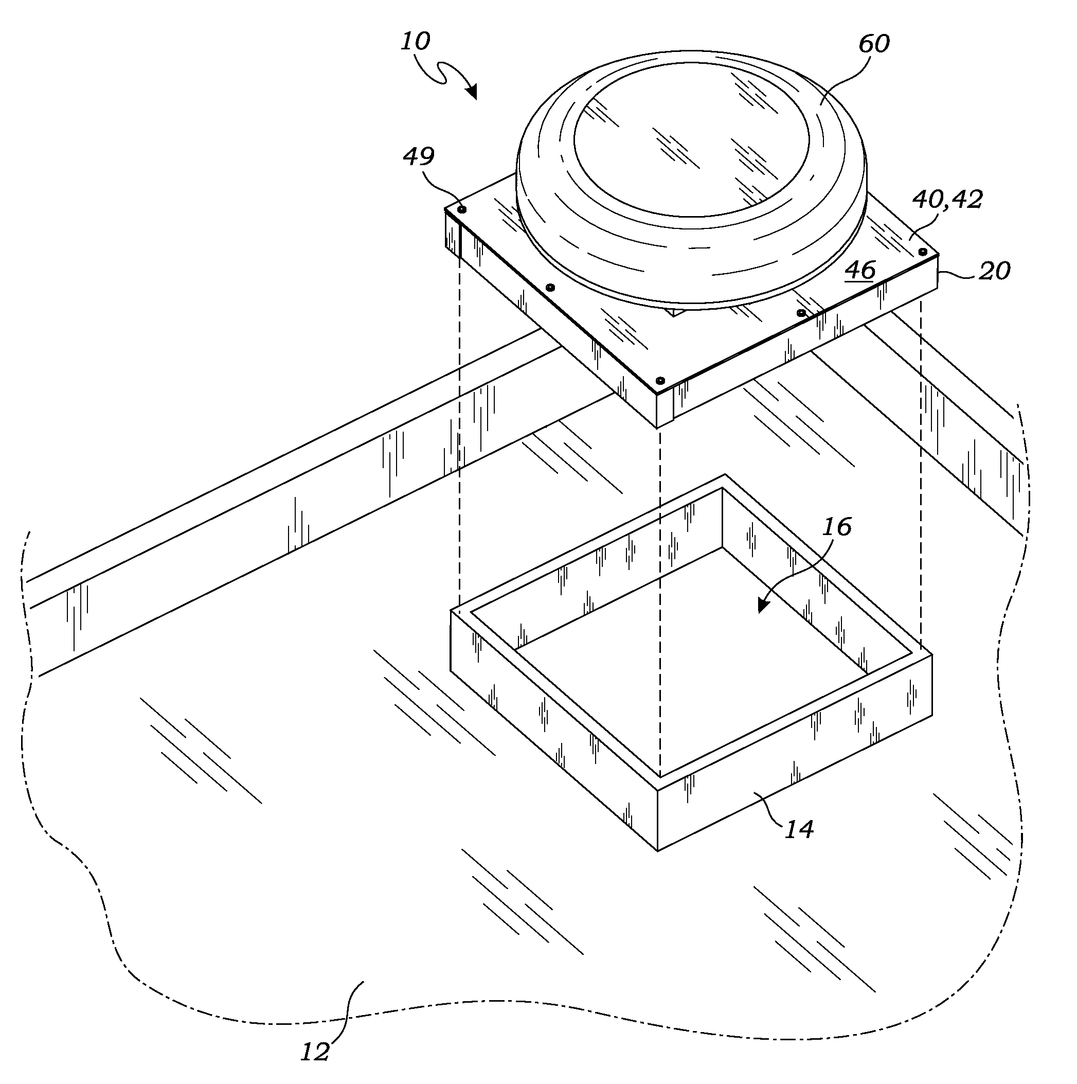
[0023]The above-described drawing figures illustrate the invention, a roof vent 10 for mounting on a roof 12 having a curb 14, to allow airflow from a building venting aperture 16 in the roof 12.

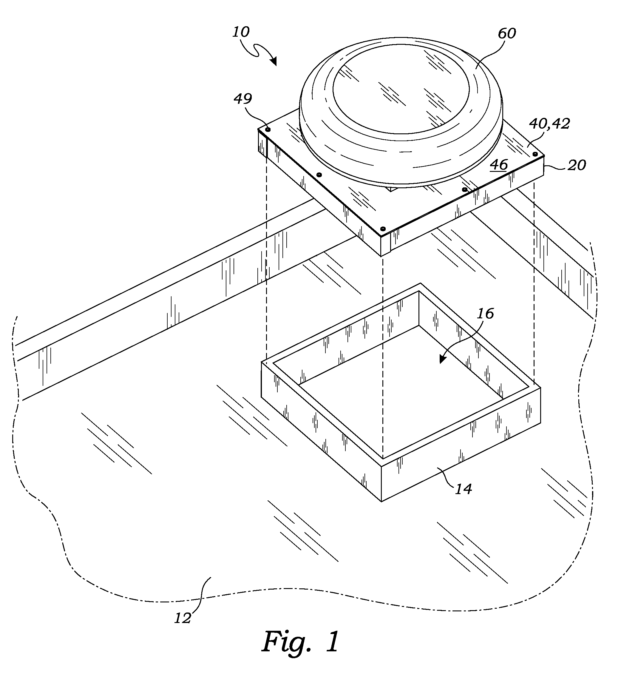
[0024]FIG. 1 is a perspective view of the roof vent 10 according to one embodiment of the present invention. As illustrated in FIG. 1, the roof vent 10 is positioned on the roof 12 for installation over and around the curb 14 of the roof 12. The roof vent 10 includes a base component 40 with a top cover 60 mounted thereupon to exclude water from the building venting aperture 16 of the roof 12. A riser box 20 mounted on the base component 40 fits over and around the curb 14 for secure mounting and to exclude water.

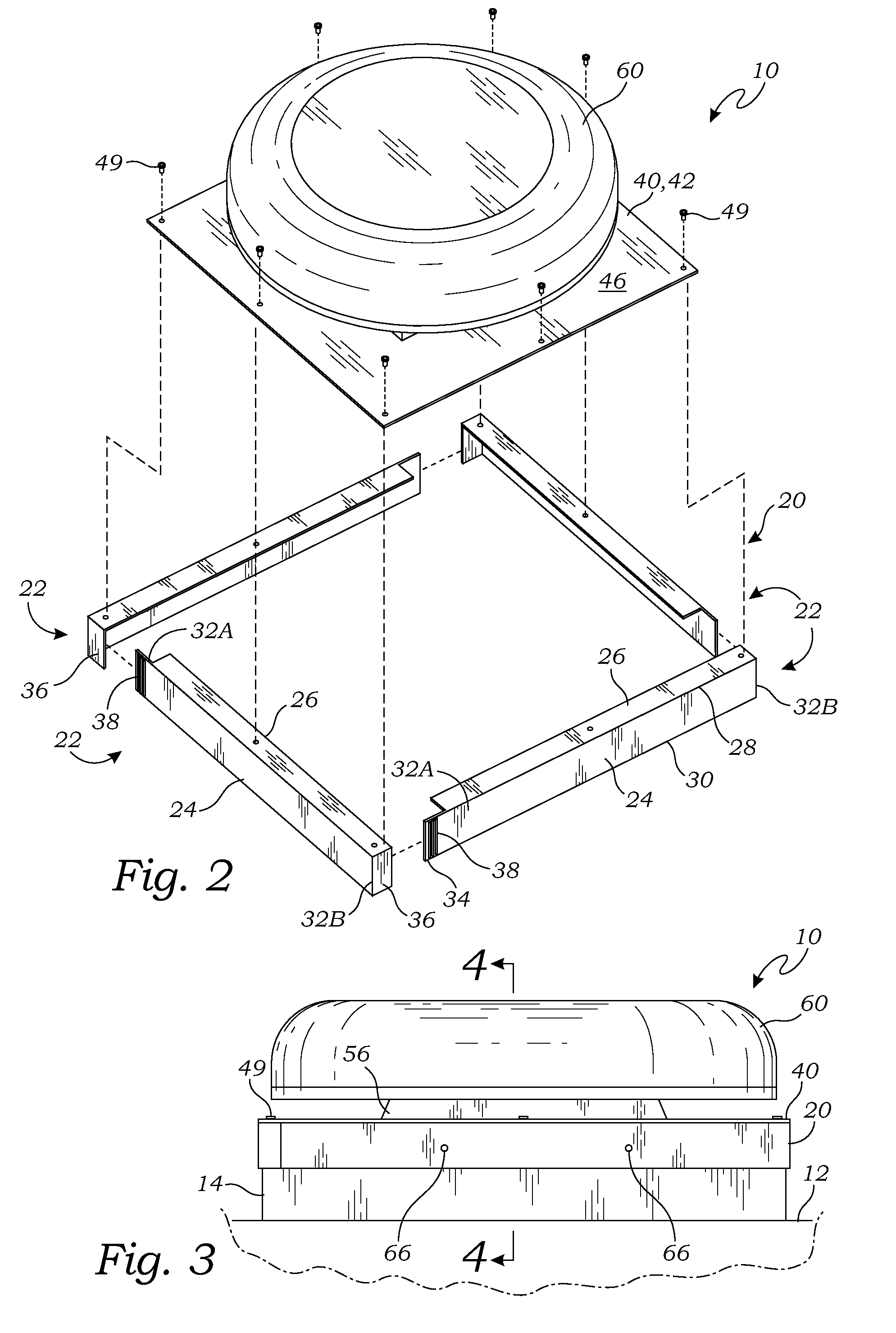
[0025]FIG. 2 is an exploded perspective view of the roof vent 10, illustrating the construction of one embodiment of the riser box 20. As illustrated in FIG. 2, the riser box 20 of this embodiment includes four wall elements 22, although other arrangements may be utilized by one ski...


PUM


Abstract

A method for installing a roof vent includes the steps of providing a base component having an outer flange having a bottom surface and surrounding a central opening; providing a top cover; mounting the top cover on the base component over the central opening to permit the air to flow through the central opening, but to exclude water from entering the central opening; and welding a riser box on the bottom surface of the base component around the central opening, the riser box being sized and shaped to fit around the curb of the roof. The base component is then mounted onto the curb such that the base component covers the building venting aperture and the riser box fits around the curb.

Description

BACKGROUND OF THE INVENTION[0001]1. Field of the Invention[0002]This invention relates generally to roof vents, and more particularly to a method for installing a plastic roof vent on a roof having a curb.[0003]2. Description of Related Art[0004]The prior art teaches a wide range of roof vents for ventilating buildings.[0005]Polston, U.S. Pat. No. 7,780,510, teaches an attic vent that is adapted for use on a roof of a residential building for venting an attic. The vent includes a generally planar base member that is suited for mounting on a sloped roof of a residence. The base component is covered by a top cover to prevent rain from penetrating the roof. While well suited for the sloped roof of an ordinary home, this vent can't be installed in commercial buildings because the planar base member is not suited for this purpose.[0006]McKee, U.S. Pat. No. 6,155,008, teaches a similar venting device that includes a base member having a vent structure therein. The device also includes a c...

Claims


Application Information

Patent Timeline
Patent Type & Authority Patents(United States)
IPC IPC(8): E04B1/00E04G23/00E04G21/00
CPCF24F7/02F24F13/084E04B1/00E04G21/00E04G23/00
Inventor POLSTON, BARRY, ROSS
Owner ROSS MFG
Why Eureka
Try Eureka