
Pulse detonation cleaning system

a cleaning system and pulse technology, applied in the direction of flush cleaning, cleaning using liquids, lighting and heating apparatus, etc., can solve the problems of leaving behind soot or other types of residu

Active Publication Date: 2014-02-18
BARRETO INVESTMENT GRP INC
View PDF105 Cites 0 Cited by
  • Summary
  • Abstract
  • Description
  • Claims
  • Application Information

AI Technical Summary

Benefits of technology

The pulse detonation cleaning system generates a powerful combined pressure wave that effectively removes soot and residues from boiler surfaces, improving cleaning efficiency and reducing pollutant emissions.

Problems solved by technology

The combustor exhaust is then largely exhausted into the atmosphere but may leave behind soot or another type of residue on the interior surface of the HRSG sidewall.

Method used


Image

  • Pulse detonation cleaning system
  • Pulse detonation cleaning system
  • Pulse detonation cleaning system

Examples


Embodiment Construction

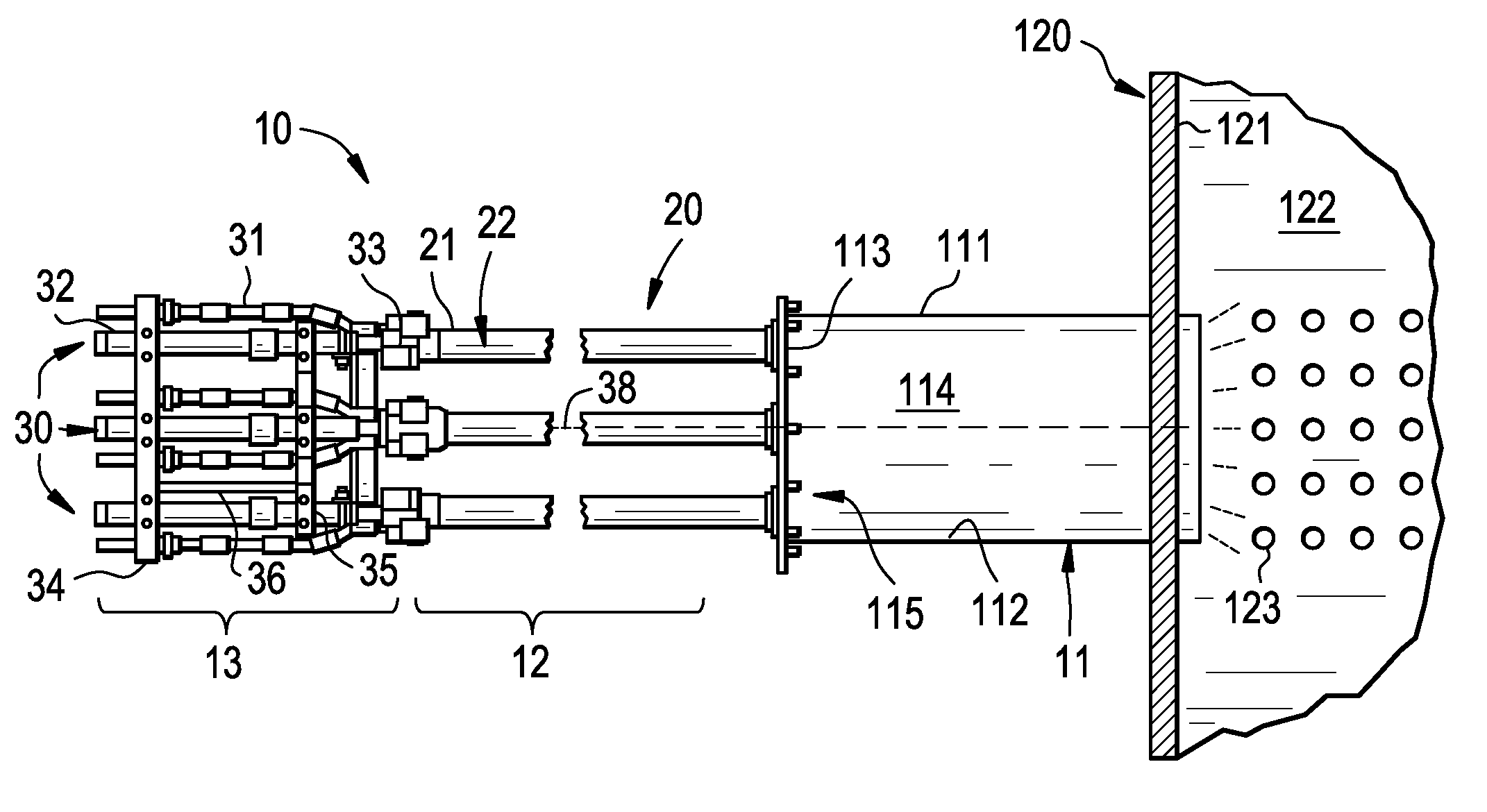
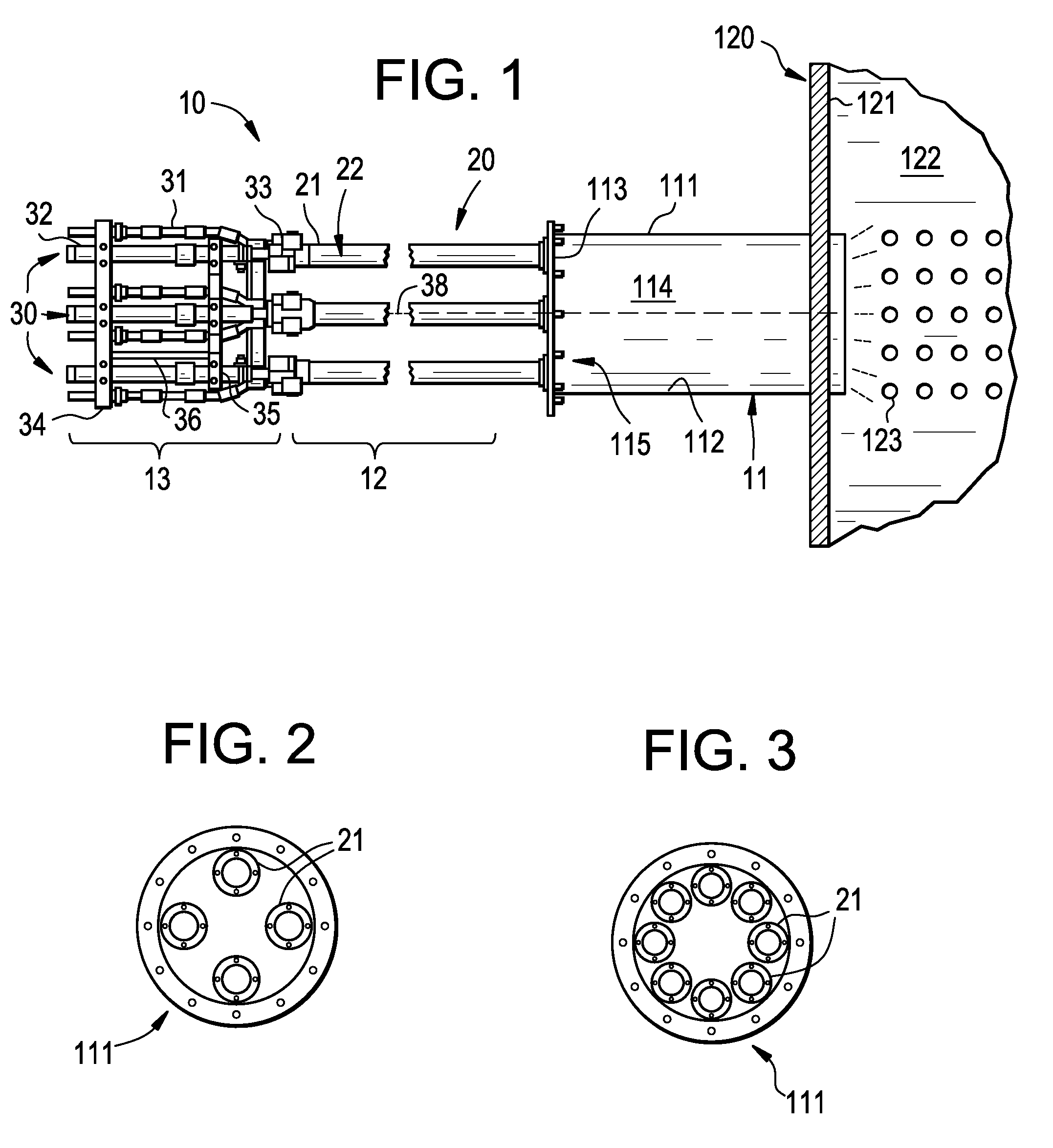
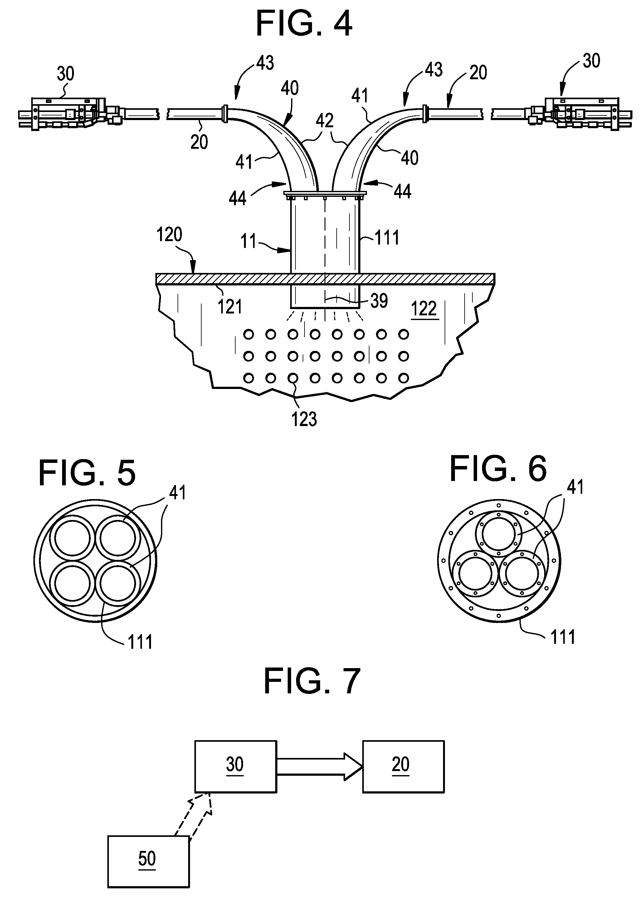
[0016]With reference to FIGS. 1-3, a pulse detonation cleaning system 10 is provided and includes a common tube 11 including a sidewall 111 having an interior facing, cylindrical surface 112 and a cover plate 113. When assembled together, the interior facing surface 112 and the cover plate 113 are cooperatively formed to define a common tube interior 114 with through-holes 115 defined at the cover plate 113 and at a radial locations proximate to the interior facing surface 112. The common tube 11 may be connected to a vessel to be cleaned. As an example, the common tube 11 may be connected to a boiler 120 of a gas turbine engine at a boiler wall 121, which is formed to define a boiler interior 122 having a heat exchanger tube banks 123 operably disposed therein such that the common tube interior 114 and the boiler interior 122 are fluidly communicative. The pulse detonation cleaning system 10 further includes a first array 12 of a plurality of elongate detonation tubes 20 and a seco...


PUM


Abstract

A pulse detonation cleaning system is provided and includes a common tube, which is fluidly coupled to a vessel, a first array, including a plurality of elongate detonation tubes arrayed about a common axis, each of the plurality of the detonation tubes being disposed upstream from and fluidly coupled to an interior of the common tube and a second array, including a plurality of detonators arrayed about the common axis, each of the plurality of the detonators being disposed upstream from and operably coupled to a corresponding one of the plurality of the detonation tubes such that actuation of each of the plurality of the detonators leads to combustion in the corresponding one of the plurality of the detonation tubes.

Description

BACKGROUND OF THE INVENTION[0001]The subject matter disclosed herein relates to a pulse detonation cleaning system.[0002]For systems that employ combustion of fossil fuels, the bi-products of the combustion operations include pollutants emitted into the atmosphere and soot deposited onto surfaces of vessel receptive of exhaust gases. These vessels include boilers, such as heat recovery steam generators (HRSG), that are coupled to combustors of, for example, gas turbine engines, such that combustor exhaust and heat may be collected in the HRSG interior for steam generation. The combustor exhaust is then largely exhausted into the atmosphere but may leave behind soot or another type of residue on the interior surface of the HRSG sidewall.[0003]In order to clean boiler surfaces, such as the interior surface of the HRSG sidewall, detonation tubes are often employed. In these cases, the detonation tubes are coupled to the boilers and are supplied with fuels and / or gases that can be fired...

Claims


Application Information

Patent Timeline
Patent Type & Authority Patents(United States)
IPC IPC(8): F28G11/00
CPCF28G7/005B08B7/0007
Inventor ZHANG, TIAN XUANCHAPIN, DAVID MICHAELTAYLOR, ROBERT WARREN
Owner BARRETO INVESTMENT GRP INC
Learn More