Air directing device for motorcycles

a technology for directing devices and motorcycles, which is applied in the direction of machines/engines, combustion-air/fuel-air treatment, and separation processes. it can solve problems such as engine overheating, engine shutdown, and engine overheating

Inactive Publication Date: 2014-02-18
JAMES JOHN CAMPBELL
View PDF9 Cites 8 Cited by
  • Summary
  • Abstract
  • Description
  • Claims
  • Application Information

AI Technical Summary

Benefits of technology

[0011]Yet another object of the invention is to provide an air directing device for a motorcycle that is easy to install.
[0014]Said air directing device for motorcycles also including an outer air directing plenum, said outer air directing plenum being horizontally disposed and having top and bottom side walls, a rear wall and an attached top plate, said outer air directing plenum having a forward facing aperture and a rear right angle aperture, said rear right angle aperture aligning with the location of the rear cylinder of a standard twin cylinder motorcycle engine, said outer air directing plenum attached to a standard air cleaner cover by one or more centrally located screws and said screws including a standoff portion that allow said outer air directing plenum top plate to remain a fixed distance from the top of said air cleaner cover, said fixed distance between the outer surface of said air cleaner housing and the inner surface of said air directing plenum top plate forming the airspace that allows cool air to travel from said forward facing aperture and out of said rear right angle aperture and onto said rear cylinder.

Problems solved by technology

Due to the location of the two cylinders with respect to air flow as the motorcycle is in forward motion, the rear cylinder tends to be cooled less than the front cylinder creating an unwanted heat buildup in the rear cylinder.
This heat buildup can be damaging to the engine and possibly cause the engine to overheat and even shut down completely.

Method used


Image

  • Air directing device for motorcycles
  • Air directing device for motorcycles
  • Air directing device for motorcycles

Examples


Embodiment Construction

[0023]Detailed descriptions of the preferred embodiment are provided herein. It is to be understood, however, that the present invention may be embodied in various forms. Therefore, specific details disclosed herein are not to be interpreted as limiting, but rather as a basis for the claims and as a representative basis for teaching one skilled in the art to employ the present invention in virtually any appropriately detailed system, structure or manner.

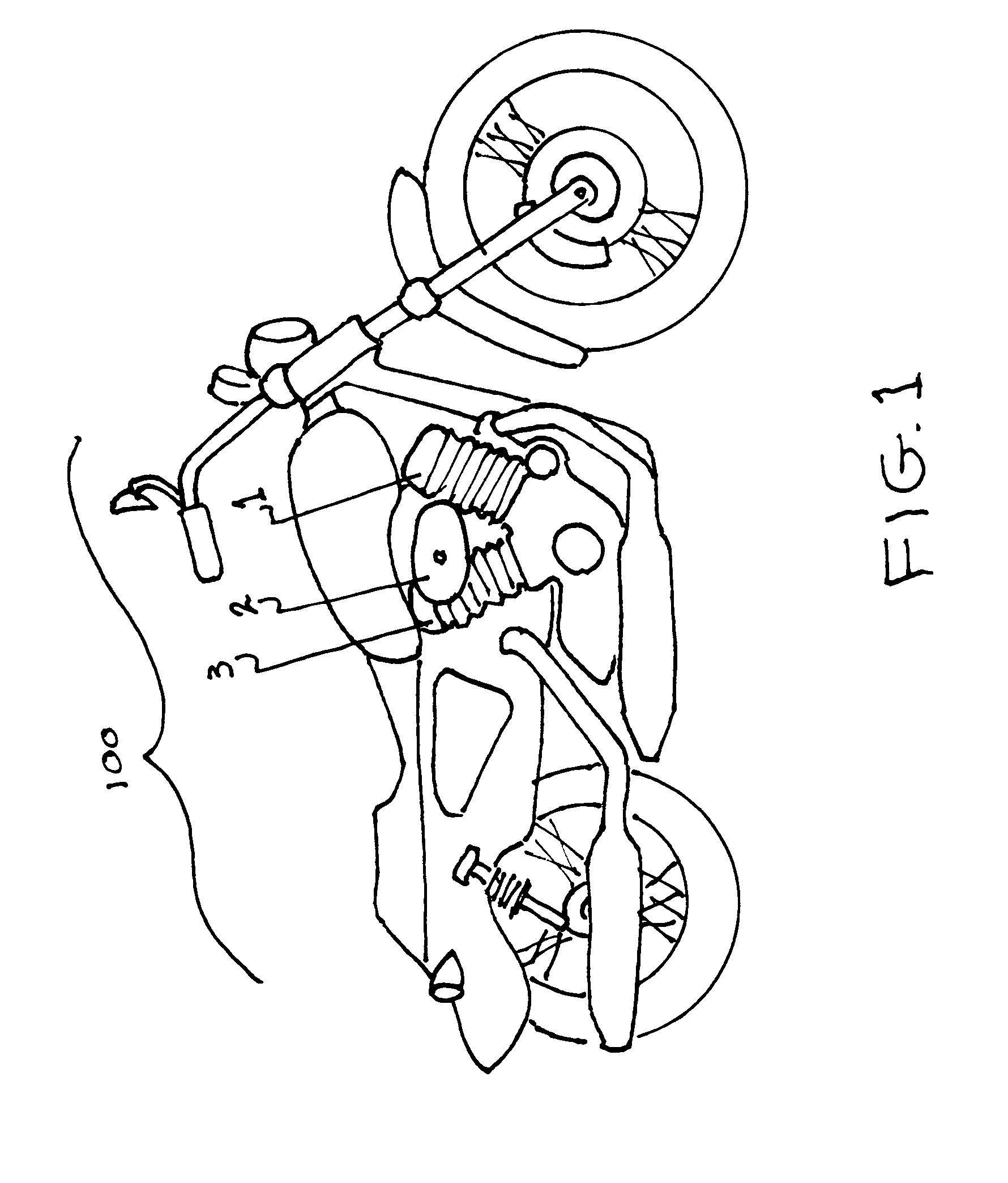
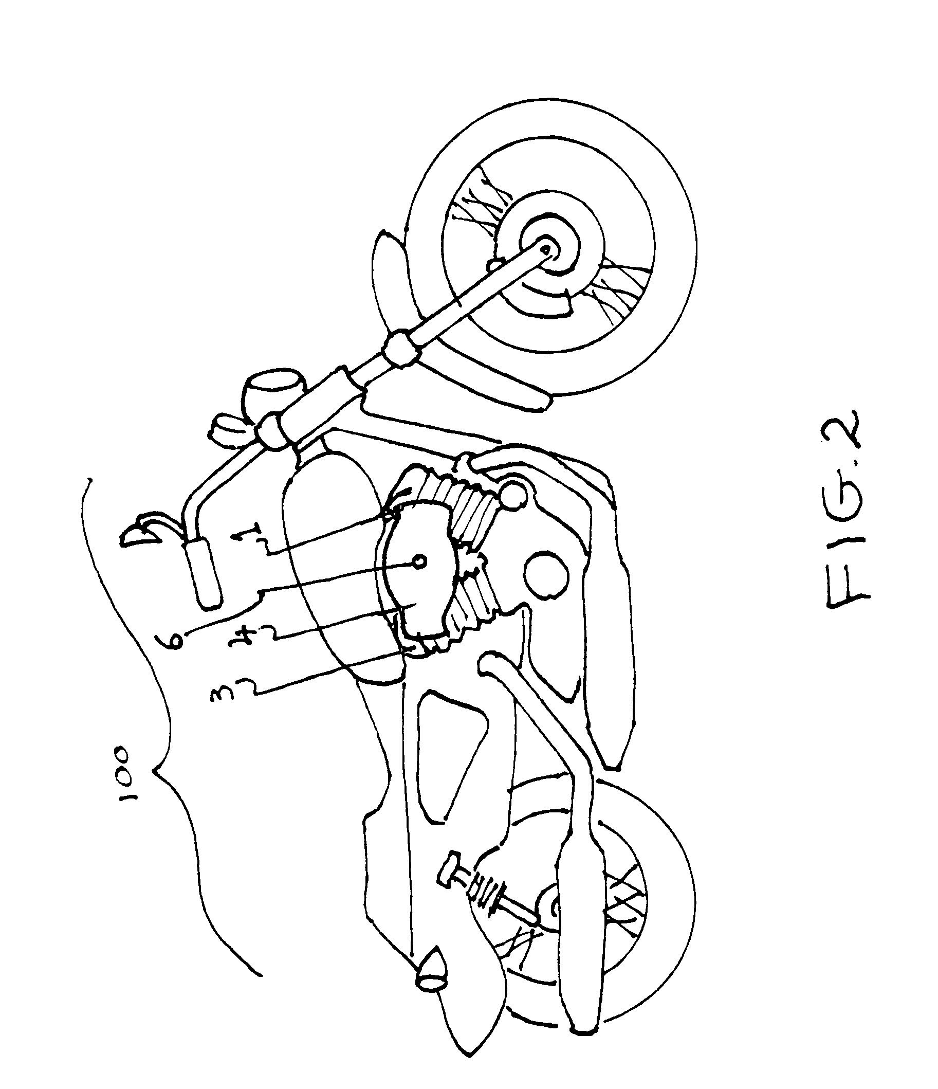
[0024]Referring now to FIG. 1 we see a side view of a twin engine Harley Davidson motorcycle 100. The forward cylinder 1 and the rear cylinder 3 form a V shape. The air cleaner assembly 2 is positioned between, and on the side of the two cylinders 1, 3. Figure two shows the same motorcycle 100 with an outer air directing plenum 4 mounted to the outside of the air cleaner assembly 2 by screw member 6.

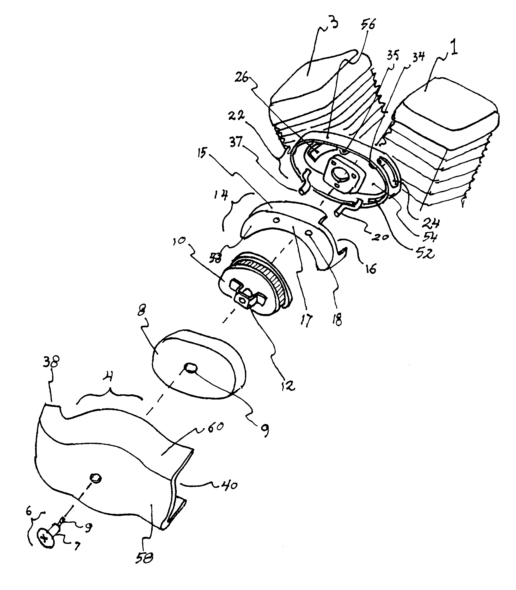
[0025]FIG. 3 is an exploded view of the invention along with several standard motorcycle parts. The standard parts include engine cylind...


PUM

PropertyMeasurementUnit
volumeaaaaaaaaaa
structureaaaaaaaaaa
V shapeaaaaaaaaaa

Abstract

An air directing device for motorcycles with an inner air directing plenum and an engine air cleaner bottom housing. The inner air directing plenum nests into the air cleaner bottom housing half. The walls of the air cleaner housing include an aperture that aligns with the forward opening of the inner air directing plenum. The air cleaner housing bottom base plate includes an aperture that aligns with the rear portion of the inner air directing plenum and also aligns with the location of the rear cylinder of a twin cylinder motorcycle engine. An optional outer air directing plenum attaches to the top housing half of an engine air cleaner. The space created between the top housing half and the inside surface of the outer plenum allows an air flow when the motorcycle is in motion that helps cool the rear cylinder of a twin cylinder motorcycle engine.

Description

CROSS REFERENCE TO RELATED APPLICATIONS[0001]Not ApplicableSTATEMENT REGARDING FEDERALLY SPONSORED RESEARCH OR DEVELOPMENT[0002]Not ApplicableDESCRIPTION OF ATTACHED APPENDIX[0003]Not ApplicableBACKGROUND OF THE INVENTION[0004]This invention relates generally to the field of motorcycle accessories and more specifically to an air directing device for motorcycle engines. Motorcycles are two wheeled motorized vehicles that have become a standard means of transportation for people in many locations around the world. Many motorcycles have air cooled engines, rather than the standard water cooled engines found in typical four wheeled vehicles.[0005]Some motorcycle engines, such as many models made by the Harley Davidson Motorcycle Company, include two cylinders where there is one forward facing cylinder that is closer to the front of the motorcycle and a second adjacent cylinder that is closer to the rear of the motorcycle. The cylinders tend to be situated in a V shaped pattern with an a...

Claims


Application Information

Patent Timeline
Patent Type & Authority Patents(United States)
IPC IPC(8): B01D46/00
CPCF02M35/10013F02M35/048F02M35/02416F02M35/10354F02M35/162F02M35/02483F02B61/02F02M35/0203F02M35/10F02M35/02
Inventor JAMES, JOHN, CAMPBELL
Owner JAMES JOHN CAMPBELL
Why Eureka
Try Eureka