Optical fiber and optical communication system including same

a technology of optical communication system and optical fiber, applied in the field of optical fiber and optical communication system, can solve the problems of deteriorating the osnr of the optical communication system as a whole, reducing the effective area of a/sub>eff /sub>in an optical fiber, and achieving the effect of long repeater span and higher power

Active Publication Date: 2014-02-18
SUMITOMO ELECTRIC IND LTD
View PDF4 Cites 5 Cited by
  • Summary
  • Abstract
  • Description
  • Claims
  • Application Information

AI Technical Summary

Benefits of technology

[0012]The present invention has been developed to eliminate the problems described above. It is an object of the present invention to provide an optical communication system which uses Raman amplification while having a structure for connecting with devices and other kinds of optical fibers, and an optical fiber employable therein. In particular, the aimed optical fiber is one having a structure for making it possible to improve the OSNR and a depressed cladding type refractive index profile and can suppress the bending loss while preventing the leakage loss from being caused by the fundamental-mode cutoff. The optical communication system as a whole employs a technique, such as digital coherent receiver technology, by which a receiver compensates for waveform distortions caused by dispersions, thereby making it unnecessary to consider any improvement for the dispersion value of the optical fiber.
[0015]The optical fiber according to the present invention can be employed in media for propagating light having a wavelength of 1625 nm or less. The optical fiber has a pure silica core with a low loss and a depressed cladding type refractive index profile which is resistant to the bending loss. The optical fiber succeeds in reducing the leakage loss by setting the fundamental-mode cutoff wavelength λFC to 2400 nm or more.
[0019]The optical communication system according to the present invention can construct an optical communication system having a repeater span of 80 km or more (a long repeater span) by using a plurality of first optical fibers and a plurality of second optical fibers. In this case, a plurality of first optical fibers are disposed at two or more locations in the repeater span of 80 km or more. A plurality of second optical fibers are connected to the first optical fibers at four or more locations in the repeater span. Each of the plurality of second optical fibers has an effective area Aeff of 85 μm2 or less at the wavelength of 1550 nm. The plurality of second optical fibers include at least those disposed at both ends of the repeater span and at one location in the repeater span. That is, in the optical communication system, the first optical fibers are assumed to connect with the second optical fibers having a small effective area Aeff of 85 μm2 or less at four or more locations, while the first optical fibers have a large effective area Aeff of 110 μm2 to 150 μm2, thereby making it possible to input Raman amplification pumping light having a higher power. On the other hand, the first optical fibers have a low transmission loss of 0.19 dB / km or less at the wavelength of 1550 nm, thereby enabling optical transmission in the long repeater span. As a result, an OSNR improvement of 1 dB or higher can be attained in the optical communication system as a whole.

Problems solved by technology

When the effective area Aeff of the transmission optical fiber is much larger than that of optical fibers at both ends of the devices or the other transmission optical fibers, the splice loss becomes greater, thereby deteriorating the OSNR of the optical communication system as a whole.
In general, enhancing the effective area Aeff in an optical fiber increases its bending loss.
In practice, the fundamental-mode propagation light begins to leak at a wavelength shorter than the fundamental-mode cutoff wavelength, thereby increasing the transmission loss.

Method used


Image

  • Optical fiber and optical communication system including same
  • Optical fiber and optical communication system including same
  • Optical fiber and optical communication system including same

Examples


Embodiment Construction

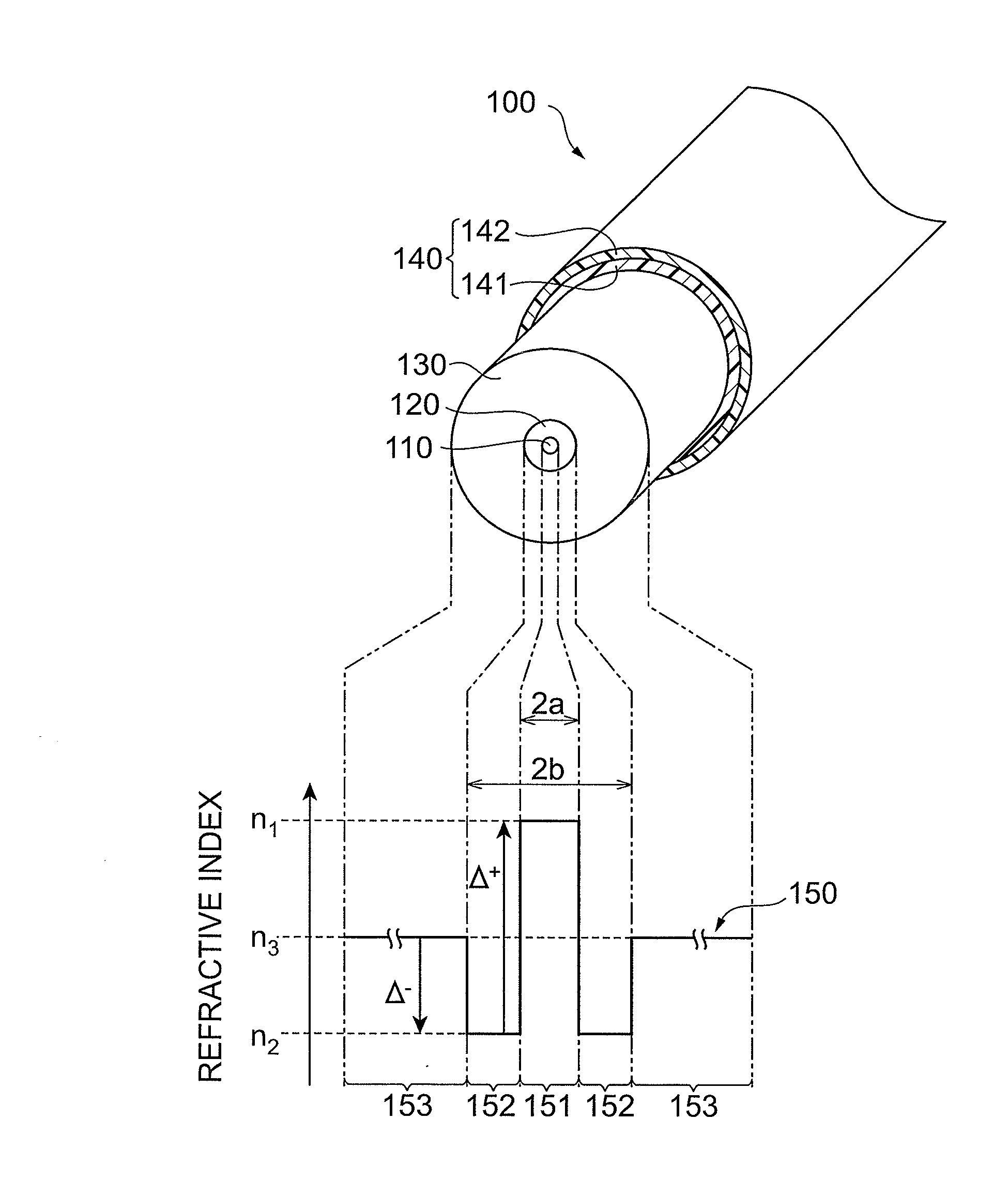
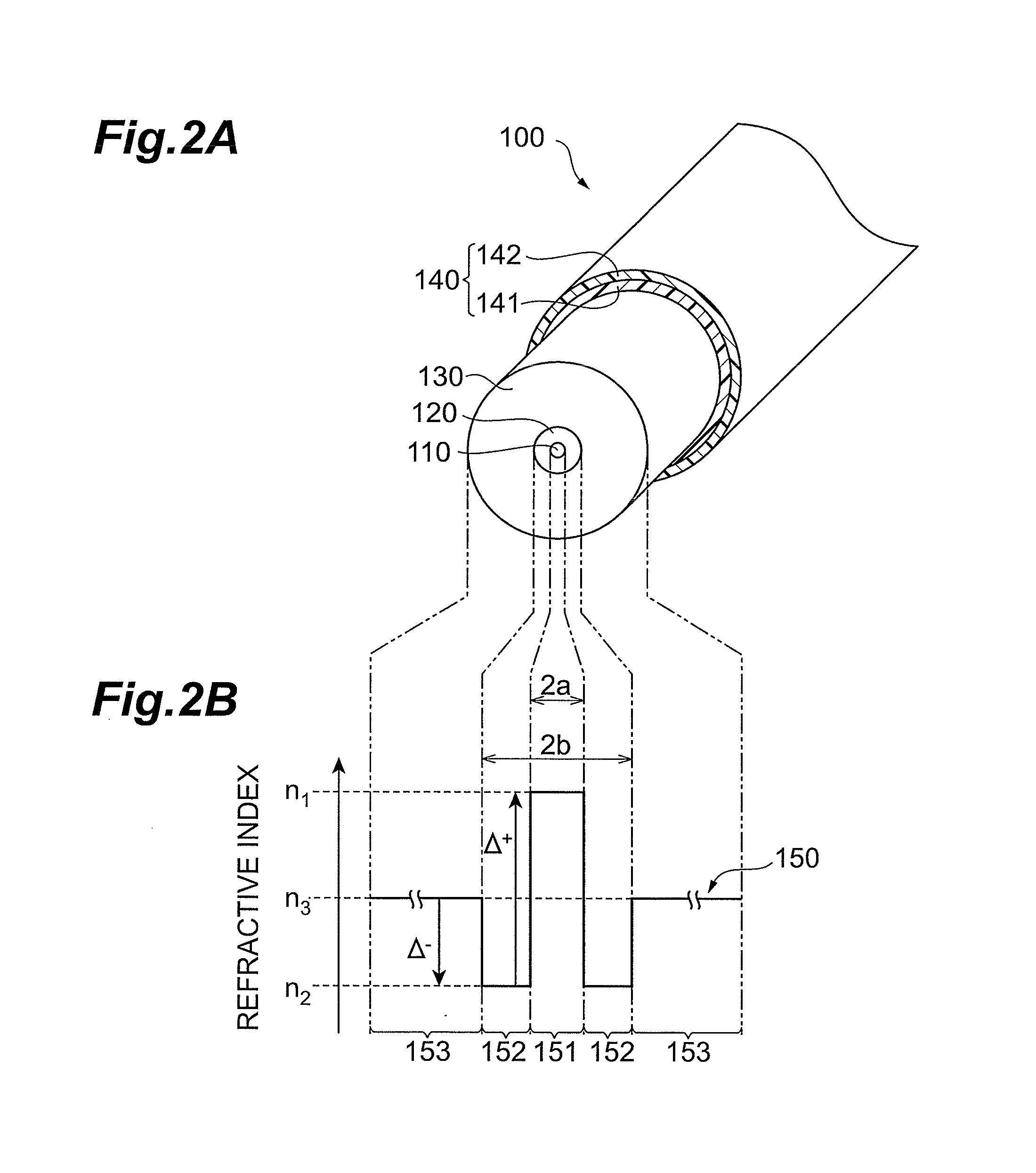
[0032]In the following, embodiments of the optical fiber and optical communication system according to the present invention will be explained in detail with reference to FIGS. 1, 2A, 2B, 3 to 6, 7A to 7C, 8, 9A, and 9B. In the description of the drawings, identical or corresponding components are designated by the same reference numerals, and overlapping description is omitted.

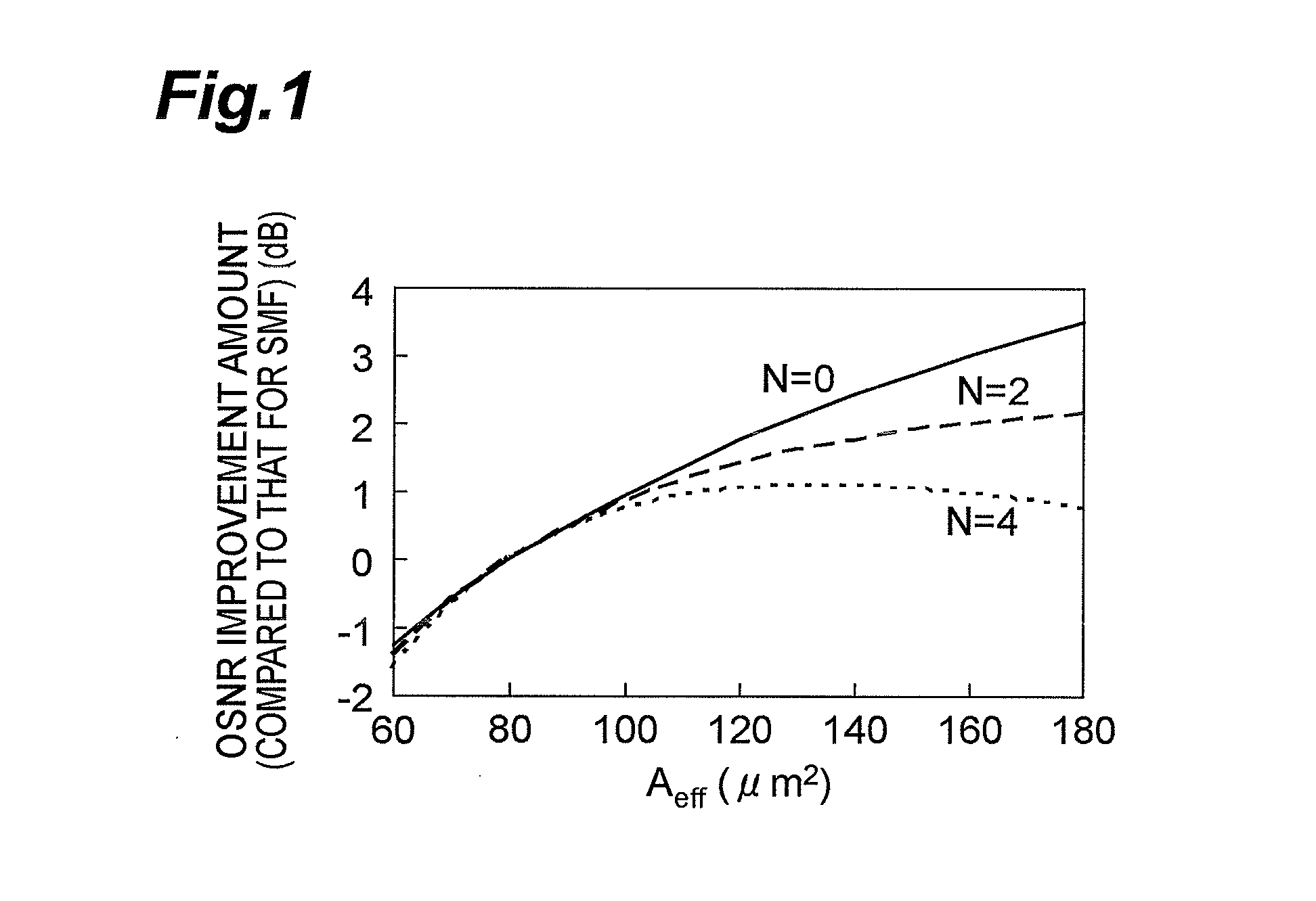
[0033]First, an optimal value of the effective area Aeff of the optical fiber according to the present embodiment, which is employable in a transmission optical fiber of an optical communication system, will be explained. From the viewpoint of characteristics of the optical fiber, the OSNR is approximately represented by the following expression (1):

OSNR(dB)∝10 log(Aeff×α(1 / km))−αsp(dB)×N−α(dB / km)×L(km)  (1)

where Aeff is the effective area of the optical fiber at a signal light wavelength, α is the transmission loss at the signal light wavelength, αsp is the splice loss, N is the number of connections per rep...


PUM


Abstract

The invention relates to an optical fiber employable in an optical communication system using Raman amplification and adapted to improve OSNR and suppress bending loss at the same time, and the like. The optical fiber is a silica-based optical fiber having a depressed refractive index profile constituted by at least a core, an inner cladding having a low refractive index, and an outer cladding, an effective area Aeff of 110 μm2 or more at the wavelength of 1550 nm, and a fiber cutoff wavelength λc of 1.3 μm or more but 1.53 μm or less. The depressed refractive index profile is designed such that the ratio Ra(=2b / 2a) of the diameter of the inner cladding to the diameter of the core is 2.5 or more but 3.5 or less and that the relative refractive index difference Δ− of the inner cladding with respect to the outer cladding is at least the relative refractive index difference Δ−min where the bending loss at the wavelength for use is minimized but not exceeding (Δ−min+0.06) %.

Description

BACKGROUND OF THE INVENTION[0001]1. Field of the Invention[0002]The present invention relates to an optical fiber which improves the optical signal-to-noise ratio (hereinafter referred to as OSNR) in a wavelength division multiplexing optical communication system using Raman amplification over a long repeater span, and an optical communication system employing such an optical fiber.[0003]2. Related Background Art[0004]Recently, in optical communication systems, techniques for compensating for waveform distortions resulting from dispersions by using digital signal processing (DSP) such as digital coherent receiver technology have been advancing in receivers. This has rapidly been increasing demands for improving the OSNR rather than dispersion values in optical transmission lines. For increasing the transmission rate without deteriorating the signal quality at a fixed repeater span in a communication system, the OSNR must be raised. For doubling the transmission rate, for example, it...

Claims


Application Information

Patent Timeline
Patent Type & Authority Patents(United States)
IPC IPC(8): H04B10/00G02B6/36G02B6/00G02B6/26
CPCG02B6/03627G02B6/02019G02B6/02395
Inventor YAMAMOTO, YOSHINORIHIRANO, MASAAKI
Owner SUMITOMO ELECTRIC IND LTD
Why Eureka
Try Eureka