Pneumatic hybrid internal combustion engine on the basis of fixed camshafts

a technology of fixed camshafts and internal combustion engines, which is applied in the direction of machines/engines, non-mechanical valves, rider propulsion, etc., can solve the problems of engine failure, engine cost, and inability to meet the needs of users, and achieves cost efficiency, improved fuel economy, and easy operation.

Active Publication Date: 2014-02-25
ETH ZZURICH
View PDF17 Cites 4 Cited by
  • Summary
  • Abstract
  • Description
  • Claims
  • Application Information

AI Technical Summary

Benefits of technology

[0021]It is an object of the invention to provide an improved, yet easy to operate and cost efficient solution for a hybrid propulsion system. Furthermore it is an object of the invention to provide an improved pneumatic propulsion system which can be adopted to standard four stroke combustion engines. Still a further object of the invention is to provide a novel approach to improve fuel economy of internal combustion engines.
[0022]The invention is directed to a pneumatic hybrid internal combustion engine having a simple and yet efficient setup. In difference to the systems known from prior art the present invention may avoid the complex setup inherent to the hybrid engines as presently available in that it is not necessary to switch between two- and four-stroke modes.
[0023]In one embodiment the pneumatic hybrid internal combustion engine comprises a first pressure vessel suitable to receive and store compressed air from a combustion chamber and a second pressure vessel suitable to receive and store compressed hot exhaust from a combustion cycle. The gas-exchange is controlled via a fast (variably) switching charge valve arranged close by or inside the combustion chamber interconnected to a slow switching valve which directs the gases to one of the pressure vessels or at least one fast switching charge valve per pressure vessel arranged close by or inside the combustion chamber. In that the at least one charge valve per combustion chamber is arranged closed-by or inside the combustion chamber the efficiency can be improved. Gases from several combustion chambers can be stored jointly in one joint pressure vessel which is interconnected to the combustion chamber via a collector conduit with several openings.

Problems solved by technology

The fully variable valves result in a very expensive and not reliable construction which is far away from today's production facility and proved technology.
Since for normal thermal operation, a high variability of intake and exhaust valves is not necessary, this solution is more complex than necessary.
Based on the information available the engine has never been commercially successful.
The described devices have a very complex Sensor input and on-demand requirements drive control logic to manage engine strokes through control of individual cylinder component states.
The connections to the gas reservoir are arranged remotely to the cylinder which significantly reduces the efficiency.
A computer controls the energy conversion function of the engine by engine and distribution valves which are arranged outside of and remotely to the combustion chamber which results in a reduced efficiency and a limitation of the possible modes of operation.
However, one problem immanent to this technology is the so-called turbo-lag during transient engine operation.
One problem of common combustion engines is their low efficiency at part load conditions.
However, all of these attempts have a very complicated setup and therefore tend to be relatively expensive.
A further problem of combustion engines results from the high emissions during cold start.
Especially gasoline engines produce a high percentage of their tailpipe emissions during cold start due to the fact that their three way catalytic converter is still cold and therefore cannot convert emissions like CO, NOx and HCs.
However, it has been shown that the time-based duty-cycling is limited to specified areas of operation parameters.
One disadvantage results from the much more complicated setup of the actuation of the inlet and exhaust valves and the significantly higher production costs.
In the pneumatic hybrid engines known from the prior art, the majority amount of the additional expenses result from the design and setup of the fully variable valve actuation which is required for all valves (inlet and exhaust valves).
In a conventional combustion engine, the conventional thermal mode is due to throttling losses not only low in part-load efficiency, but also due to the blow-off when the exhaust valves are opened and exhausted gases with high pressure and temperature are blown off through the exhaust.
Using the pneumatic motor mode, a high internal energy of a gas also leads to more energy being available for propulsion and therefore decreases fuel consumption.
When supercharging an engine with high torque, additional fuel is burned and the risk of destructive motor knocking has to be considered.
This requires fully variable valve actuation for inlet and exhaust valves and it requires therefore a very difficult setup.
However, the efficiency may thereby be reduced.

Method used


Image

  • Pneumatic hybrid internal combustion engine on the basis of fixed camshafts
  • Pneumatic hybrid internal combustion engine on the basis of fixed camshafts
  • Pneumatic hybrid internal combustion engine on the basis of fixed camshafts

Examples


Embodiment Construction

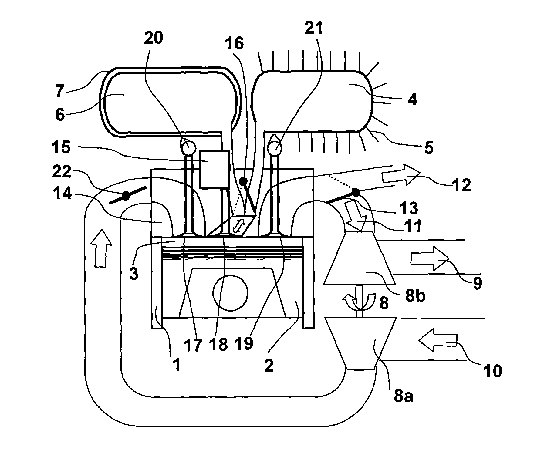
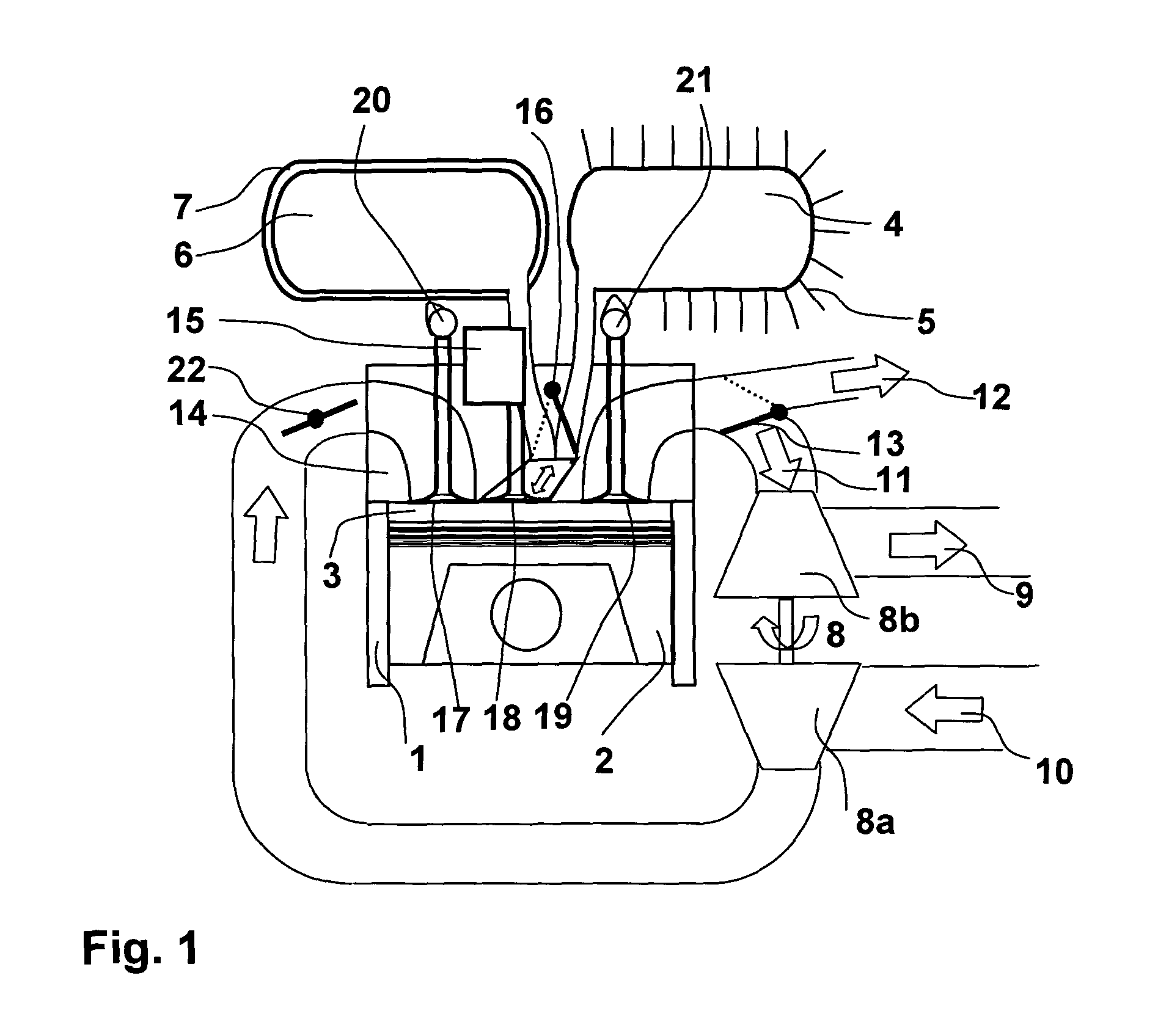
[0063]FIG. 1 schematically shows a configuration of a combustion engine according to the present invention. An engine block (cylinder) 1, a cylinder head 14 and a piston 2 are encompassing a combustion chamber 3 with a variable volume. Ambient air 10 is aspired from the environment and compressed by a compressor 8a of a turbocharger 8. In the shown embodiment the air flow is controlled by a throttle 22 arranged in the intake area of the engine and admitted into the combustion chamber 3 via an inlet valve 17, which is mechanically actuated by a camshaft 20. The camshaft 20 is mechanically interconnected and driven by an engine crankshaft (not shown in detail). A charge valve 18 which interconnects a first and a second pressure tank 4, 6 with the combustion chamber is actuated by a charge valve actuator 15 in fully variable manner. This means, that while the inlet and exhaust valves 17, 19 are mechanically interconnected to the crankshaft, the charge valve can be operated completely i...


PUM


Abstract

The present disclosure relates to an pneumatic hybrid internal combustion engine with at least one combustion chamber composed of a cylinder in which a piston is arranged mechanically interconnected to a crank shaft via a piston rod. An inlet valve and an exhaust valve are both mechanically interconnected via a valve gear to the crank shaft. The engine further includes at least one charge valve which is actuated by a charge valve actuator in a fully variable manner such that the engine can be operated in a four stroke hybrid mode.

Description

CROSS REFERENCE TO RELATED APPLICATIONS[0001]The present application is a 35 U.S.C. §371 National Phase conversion of PCT / EP2008 / 007908, filed Sep. 19, 2008, which claims benefit of European Application No. 07018673.9, filed Sep. 22, 2007, the disclosure of which is incorporated herein by reference. The PCT International Application was published in the English language.BACKGROUND[0002]1. Field of the Disclosure[0003]The present invention relates to an improved internal combustion engine which can be operated in a four-stroke pneumatic modes according to the preamble of annexed patent claims.[0004]2. Related Art[0005]A plethora of suggestions and patents have been made in more than 100 years development to increase the overall efficiency of internal combustion engines as e.g. used in vehicles.[0006]A rather old general concept for increasing the efficiency of an engine driven vehicle is directed to the recuperation of vehicle brake energy otherwise lost in friction brakes. This can ...

Claims


Application Information

Patent Timeline
Patent Type & Authority Patents(United States)
IPC IPC(8): B60K1/00
CPCF02B29/0493F02M25/0743Y02T10/18F02D13/0276F01L13/06F02B21/02F01L13/04F02B27/00F02M26/37Y02T10/12
Inventor DONITZ, CHRISTIANONDER, CHRISTOPHERVASILE, JULIANGUZZELLA, LINOHIGELIN, PASCALCHAMAILLARD, YANNCHARLET, ALAIN
Owner ETH ZZURICH
Why Eureka
Try Eureka