
Method for manufacturing electrophotographic elastic roller

a manufacturing method and elastic roller technology, applied in the direction of manufacturing tools, electrographic processes, instruments, etc., can solve the problems of affecting the resulting image, affecting the thickness of the elastic layer, and high stress on the developing agent, so as to achieve good thickness precision, small deflection, and good dimensional precision

Active Publication Date: 2014-03-04
CANON KK
View PDF2 Cites 0 Cited by
  • Summary
  • Abstract
  • Description
  • Claims
  • Application Information

AI Technical Summary

Benefits of technology

[0014]It is an object of the present invention to provide a method for manufacturing a stable and low-cost electrophotographic elastic roller having a good dimensional precision, in particular, a small deflection (a good thickness precision of the elastic layer) and good repetitive reproducibility.
[0021]According to the present invention, it is possible to provide a method for manufacturing a stable and low-cost electrophotographic elastic roller having a good dimensional precision, in particular, a small deflection (a good thickness precision of the elastic layer) and good repetitive reproducibility.

Problems solved by technology

Repeating these processes will result in that the developing agent undergoes high stress.
If a stable contact state cannot be maintained, the feed amount of the developing agent may vary and also the pressure distribution of the photosensitive drum may vary thereby affecting the resulting image.
For example, in a contact development scheme, since the developing roller is in contact with the surface of the photosensitive drum as described above, insufficient precisions in the outer dimensions and thickness will cause variations in the nip width and nip force between the photosensitive drum and the roller leading to image defects such as density variations.
However, it is inevitable to repeat the process of overcoating the formed elastic layer with an elastic layer material and the process of removing the solvent, resulting in a very low productivity.
Moreover, in the elastic rollers manufactured in this way, since many processes are repeated causing the tolerances in the dimensional precision and the deflection (thickness precision) to build up, it is difficult to control the dimensional precision and the deflection (thickness precision) as an elastic roller.

Method used


Image

  • Method for manufacturing electrophotographic elastic roller
  • Method for manufacturing electrophotographic elastic roller
  • Method for manufacturing electrophotographic elastic roller

Examples


example 1

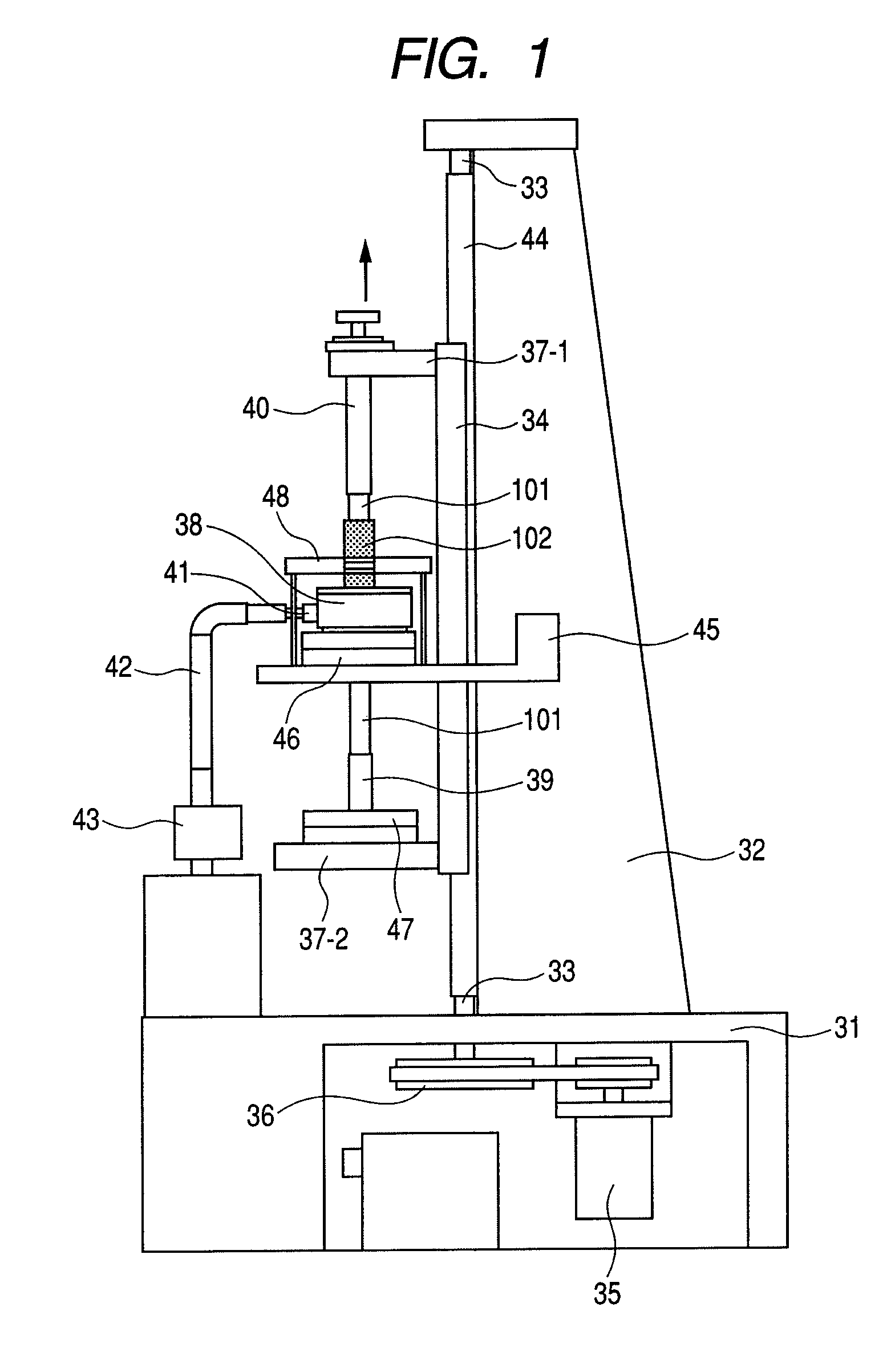
[0095]As a coating apparatus for coating an elastic layer material to a shaft core body 101, an upright ring coating machine including a circular coating head 38 of the form shown in FIG. 1 was used.

[0096](Preparation of Elastic Layer Material)

[0097]10 parts by mass of carbon black (MA11, Mitsubishi Chemical Corporation) was added to 100 parts by mass of each of a liquid A of an addition reaction cross-linked type liquid silicone rubber (DY35-1265A, Dow Corning Toray Co., Ltd.) and a liquid B of an addition reaction cross-linked type liquid silicone rubber (DY35-1265B, Dow Corning Toray Co., Ltd.), respectively. These are mixed and deformed for 30 minutes by a planetary mixer. Thereafter, the liquid A and the liquid B mixed with carbon black were respectively set in a material tank associated with the coating apparatus and were forwarded to a static mixer by using a pressure pump to mix the liquid A and the liquid B with a mass ratio of 1:1. This liquid silicone rubber mixture was u...

example 2

[0106]Electrophotographic elastic rollers were fabricated in the same manner as in Example 1 except that for the time until the circular slit portion of the circular coating head 38 reached the position 101-2, the position of the circular coating head 38 was corrected (moved) by 5% of the maximum moving amount to the direction of the maximum deflection coordinate.

[0107]Thus, 1000 electrophotographic elastic rollers were fabricated in the same manner. The distribution of the deflections in the longitudinal direction (longitudinal position 101-2) of the gripped and fixed shaft core body 101 of the shaft core bodies 101 that were incorporated at that time, and the distribution of the deflections of 1000 elastic rollers that were fabricated are shown in Table 1. Among the electrophotographic elastic rollers fabricated in the present example, 100% of them showed a deflection of less than 30 μm meaning that electrophotographic elastic rollers with small deflections were able to be produce...

example 3

[0108]Electrophotographic elastic rollers were fabricated in the same manner as in Example 1 except that for the time until the circular slit portion of the circular coating head 38 reached the position 101-2, the position of the circular coating head 38 was corrected (moved) by 50% of the maximum moving amount to the direction of the maximum deflection coordinate.

[0109]Thus, 1000 electrophotographic elastic rollers were fabricated in the same manner. The distribution of the deflections in the longitudinal direction (longitudinal position 101-2) of the gripped and fixed shaft core body 101 of the shaft core bodies 101 that were incorporated at that time, and the distribution of the deflections of 1000 elastic rollers that were fabricated are shown in Table 1. Among the electrophotographic elastic rollers fabricated in the present example, 100% of them showed a deflection of less than 30 μm meaning that electrophotographic elastic rollers with small deflections were able to be produc...


PUM

PropertyMeasurementUnit
viscosityaaaaaaaaaa
viscosityaaaaaaaaaa
yield stressaaaaaaaaaa

Abstract

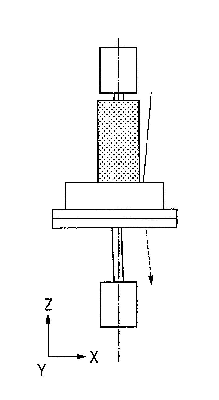
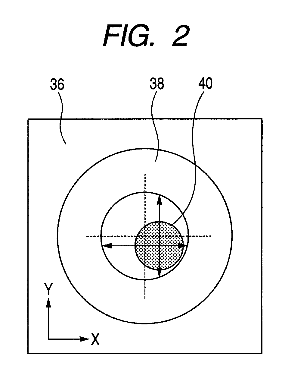
A method for manufacturing a low-cost electrophotographic elastic roller having a good dimensional precision is provided. In that method, in which both end parts of a shaft core body are gripped and fixed in a vertical direction, an inclination of a central axis is corrected, a circular coating head including a circular slit is used so that the shaft core body is moved in the direction, and a elastic layer material is ejected from the slit to be coated on the shaft core body, the method includes: a maximum deflection coordinate in a longitudinal direction of the shaft core body is detected with a central axis of the shaft core body as a base point coordinate before coating; a central position of the head is moved at constant from the base point to the maximum during coating, and the position is moved to the base point after the head has reached the maximum.

Description

BACKGROUND OF THE INVENTION[0001]1. Field of the Invention[0002]The present invention relates to a method for manufacturing an electrophotographic elastic roller for use in image forming apparatuses such as printers and copy machines, and electrophotographic process cartridges.[0003]2. Description of the Related Art[0004]Conventional electrophotographic recording apparatuses will be described below. Such an apparatus incorporates an image forming part in its main unit, and an image is formed by undergoing cleaning, charging, latent imaging, developing, transfer, and fixing processes. An image forming part includes a photosensitive drum which is an image carrying body, a cleaning part, a charging part, a latent image forming part, a developing part, and a transfer part. An image on the photosensitive drum, which is formed at the image forming part, is transferred to a recording material with a transfer member and conveyed, thereafter being heated and pressurized at a fixing part to b...

Claims


Application Information

Patent Timeline
Patent Type & Authority Patents(United States)
IPC IPC(8): B22D11/12
CPCG03G15/0818G03G2215/0861G03G2215/1614G03G2215/0863Y10T29/49826Y10T29/49563Y10T29/4956Y10T29/49982
Inventor SUZUKI, AKIHIROICHIGE, HIDETOSHI
Owner CANON KK
Learn More