System and method for liquid reductant injection

a liquid reductant and injection system technology, applied in the field of systems and methods, can solve the problems of increased cost associated with heating and freezing safety components of the urea storage tank and injection system, inability to deliver urea to the pick-up tube of the injection system, and fuel economy may be reduced, so as to ensure the functionality and survivability of the injection system, and reduce the effect of nox

Inactive Publication Date: 2014-03-04
FORD GLOBAL TECH LLC
View PDF12 Cites 7 Cited by
  • Summary
  • Abstract
  • Description
  • Claims
  • Application Information

AI Technical Summary

Benefits of technology

[0004]At ambient temperatures of less than −11° C., the aqueous urea solution (comprising 32.5% urea and 67.5% water) may freeze in the on board urea storage tank. Thus, a pick up tube of the injection system may not be able to deliver urea to the injector for delivery to the exhaust gas and NOx reduction. In one approach, the urea storage tank includes an electric heating system to warm the frozen urea. Further, components of the urea storage tank and urea injection system may have a freeze-safe design to assure functionality and survivability of the injection system over multiple freeze / thaw cycles.
[0005]The inventors of the present application have recognized a problem in such previous solutions. First, there may be increased cost associated with the heating and freeze-safe components for the urea storage tank and urea injection system. Second, fuel economy may be decreased by using energy produced by the vehicle to heat the entire urea tank, and such heating may take an extended duration, thus reducing the amount of exhaust gases that can be treated catalytically with the reductant, and thus increasing exhaust emissions overall.
[0007]In this way, by including ethanol in the reductant solution, a freezing point temperature of the liquid reductant may be reduced. As such, the occurrences of reductant freezing may be reduced. If the temperature drops below a precipitate forming threshold, the liquid reductant may be heated by the pick-up tube. Thus, the liquid reductant injection system consumes less energy because heating of the storage tank is not required. Because of these features, the system may require less energy during operation and overall fuel economy may be improved. Further still, pumping of the liquid reductant injection system in a reverse direction may clear delivery and return lines of remaining liquid reductant. This may prevent reductant from precipitating and / or freezing in the delivery and return lines during ambient temperature conditions below the liquid reductant precipitation and freezing points, thereby reducing clogging and improving efficiency of NOx reduction.

Problems solved by technology

Thus, a pick up tube of the injection system may not be able to deliver urea to the injector for delivery to the exhaust gas and NOx reduction.
First, there may be increased cost associated with the heating and freeze-safe components for the urea storage tank and urea injection system.
Second, fuel economy may be decreased by using energy produced by the vehicle to heat the entire urea tank, and such heating may take an extended duration, thus reducing the amount of exhaust gases that can be treated catalytically with the reductant, and thus increasing exhaust emissions overall.

Method used


Image

  • System and method for liquid reductant injection
  • System and method for liquid reductant injection
  • System and method for liquid reductant injection

Examples


Embodiment Construction

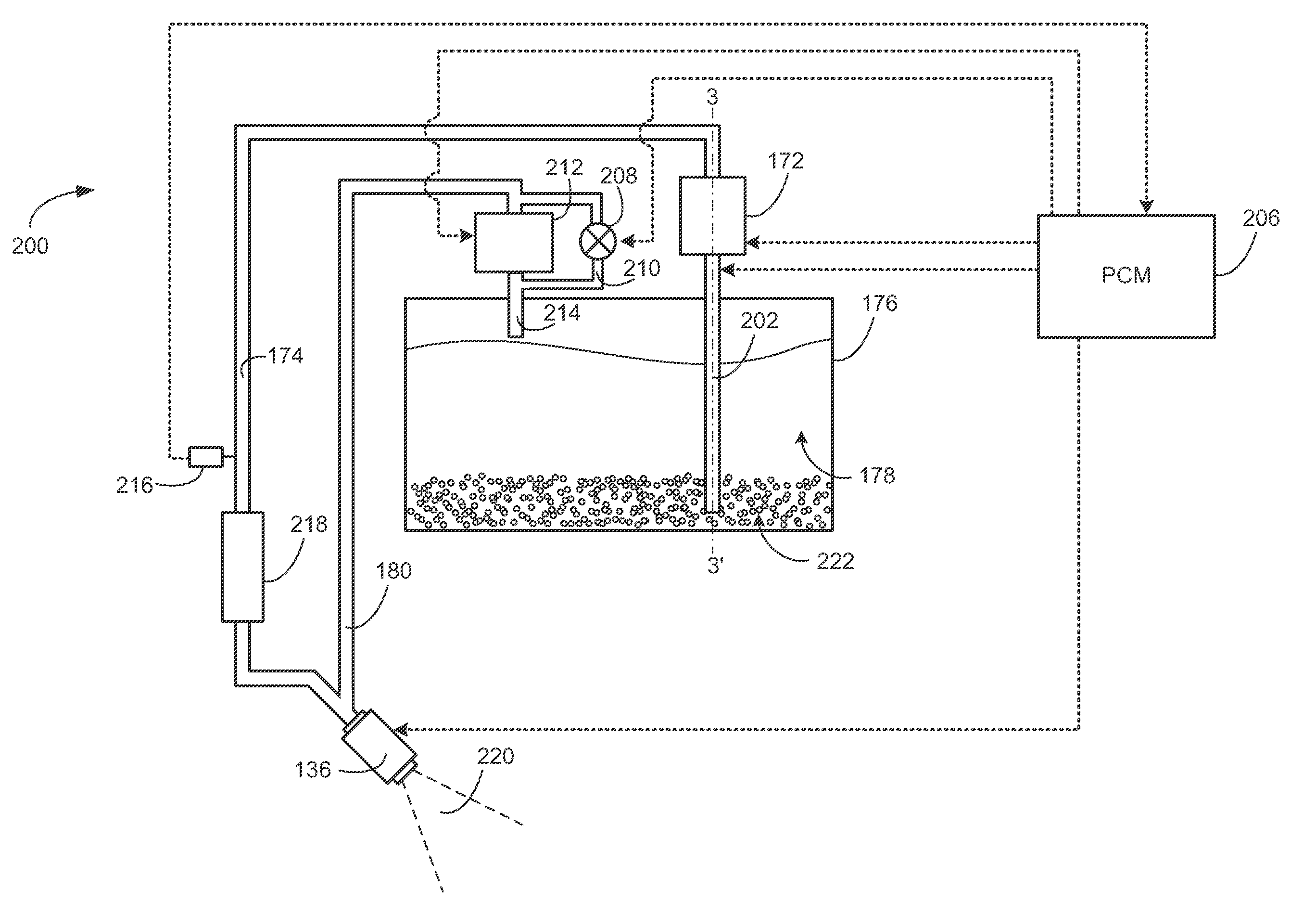
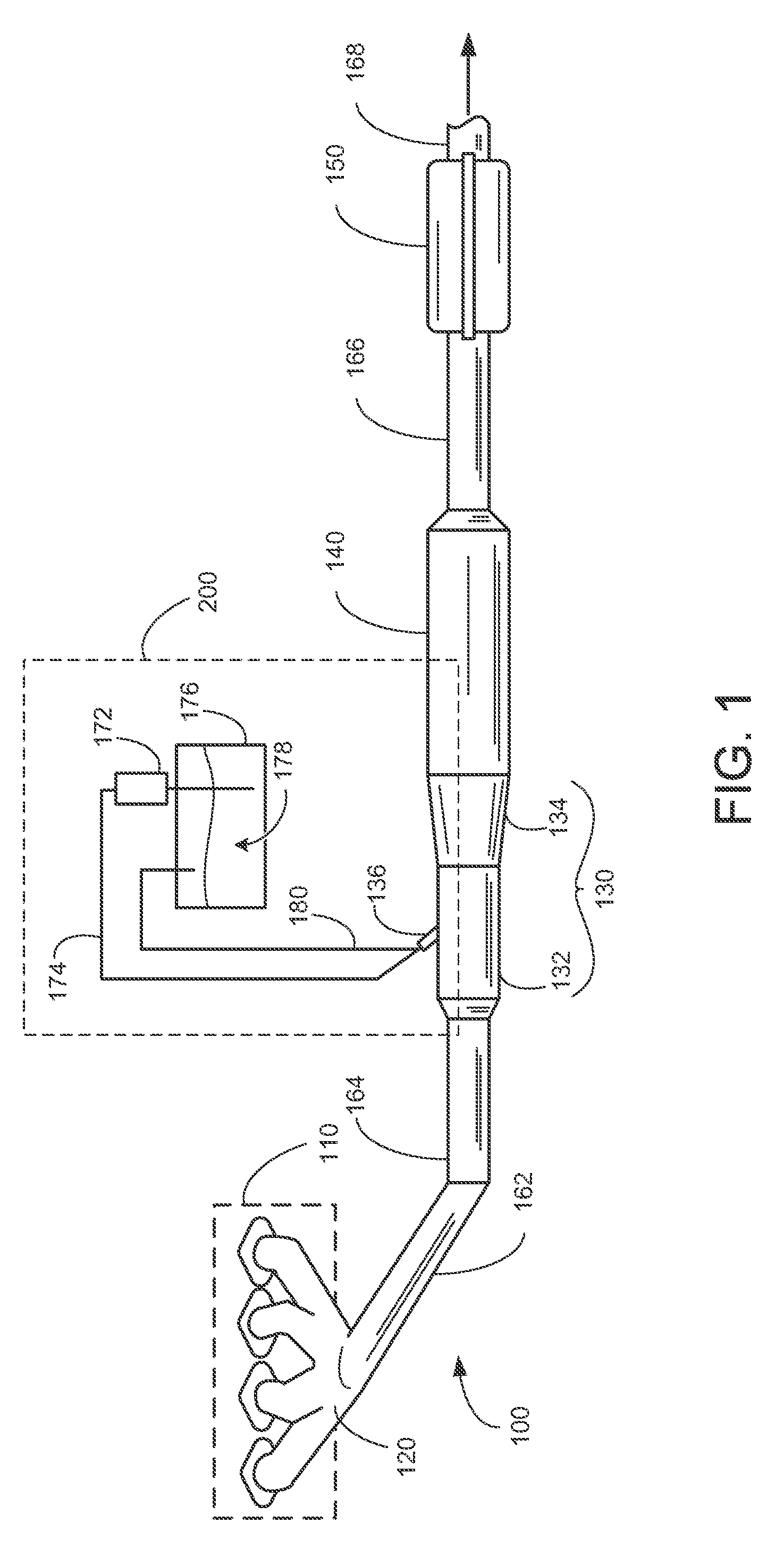
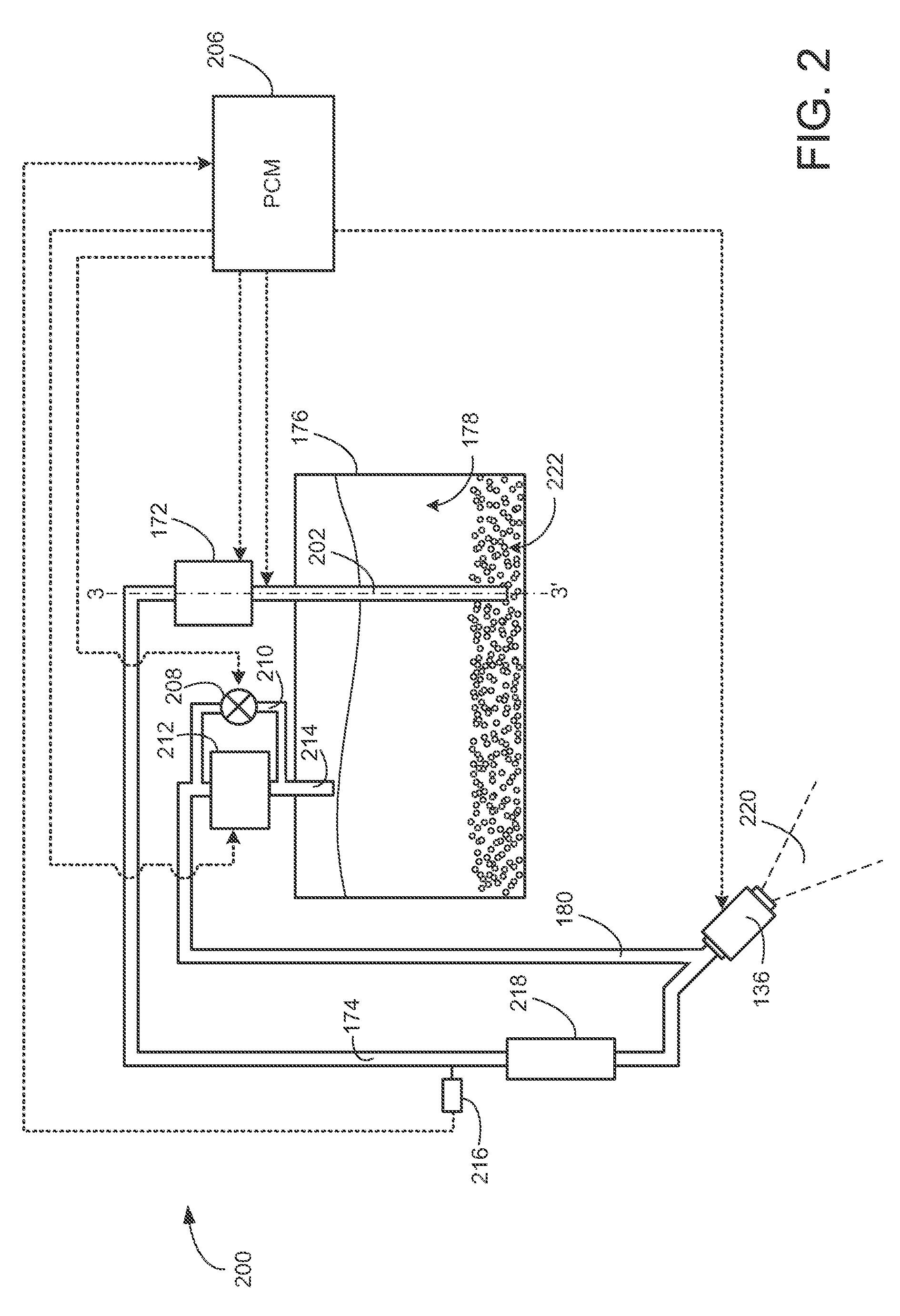
[0014]Embodiments of an exhaust system and a urea injection system for use with an aqueous urea and ethanol solution are disclosed herein. Such a urea injection system may be utilized for exhaust gas treatment by NOx reduction in various ambient temperature conditions. More specifically, the urea injection system may be used to treat exhaust gas in ambient temperatures below a normal freezing temperature of aqueous urea, as described in more detail hereafter.

[0015]FIG. 1 includes an example exhaust system for a vehicle with a diesel engine including a urea injection system. FIG. 2 shows a more detailed view of the urea injection system. FIG. 3 shows a cross section of a heated pick up tube along the 3-3′ axis of FIG. 2. FIG. 4 includes a flow chart of an example method for operating the urea injection system of FIG. 2 in either of a normal mode or a precipitate dissolving mode. FIG. 5 includes a flow chart of an example method for the precipitate dissolving mode.

[0016]More specifica...


PUM


Abstract

A method for operating a liquid reductant injection system is provided. The method includes storing a reductant mixture of ethanol, water, and urea; drawing the stored mixture into an electrically heated pick-up tube for delivery via a delivery line to the exhaust by operating a pump in a first direction; and, clearing a return line that returns the stored mixture or the delivery line by operating the pump in a second, reverse, direction. In this way, by including ethanol in the reductant solution, a freezing point temperature of the liquid reductant may be reduced.

Description

CROSS REFERENCE TO RELATED APPLICATION[0001]The present application claims the benefit of and priority to U.S Provisional Patent Application No. 61 / 475,834, filed on Apr. 15, 2011, entitled “SYSTEM AND METHOD FOR LIQUID REDUCTANT INJECTION”, the content of which is incorporated herein by reference for all purposes.TECHNICAL FIELD[0002]The present application relates to a system and a method for delivering liquid reductant solution in an exhaust treatment system of a vehicle.BACKGROUND AND SUMMARY[0003]Many vehicles utilize catalysts in exhaust systems to reduce emissions. In lean exhaust conditions, such as with regard to diesel exhaust or other lean burning conditions, a catalyst may utilize reductant other than burnt fuel. One such aftertreatment device is a Selective Catalytic Reduction (SCR) system, which uses a catalyst to convert NOx to nitrogen and water. A urea-based SCR catalyst may use gaseous ammonia as the active NOx reducing agent, in which case an aqueous solution of u...

Claims


Application Information

Patent Timeline
Patent Type & Authority Patents(United States)
IPC IPC(8): F01N3/20
CPCF01N2610/02Y02T10/47Y02T10/24F01N3/208F01N2610/1473F01N9/00Y02T10/12Y02T10/40
Inventor LEVIN, MICHAELSHAIKH, FURQAN ZAFARMCCARTHY, THOMAS A.ZIMMERMAN, BRET ALAN
Owner FORD GLOBAL TECH LLC
Why Eureka
Try Eureka